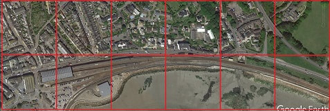
Continuing the experiments with new scales and prototypes: Stephenson's Rocket on the Liverpool and Manchester Railway c1828 in 1:350 scale.
|
|
|
Continuing the experiments with new scales and prototypes: Stephenson's Rocket on the Liverpool and Manchester Railway c1828 in 1:350 scale.
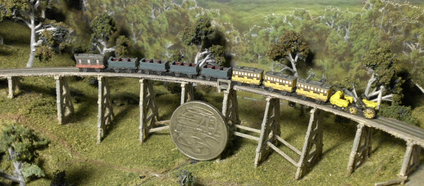
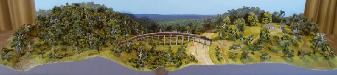
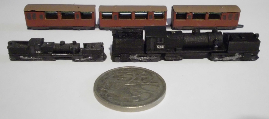 The 1:220 scale experiments are complete for now, with the G42 Garratt properly articulated and running, as well as versions of the NBH and NBHC carriages. They all run, so this scale and prototype is definitely an option for a future layout.
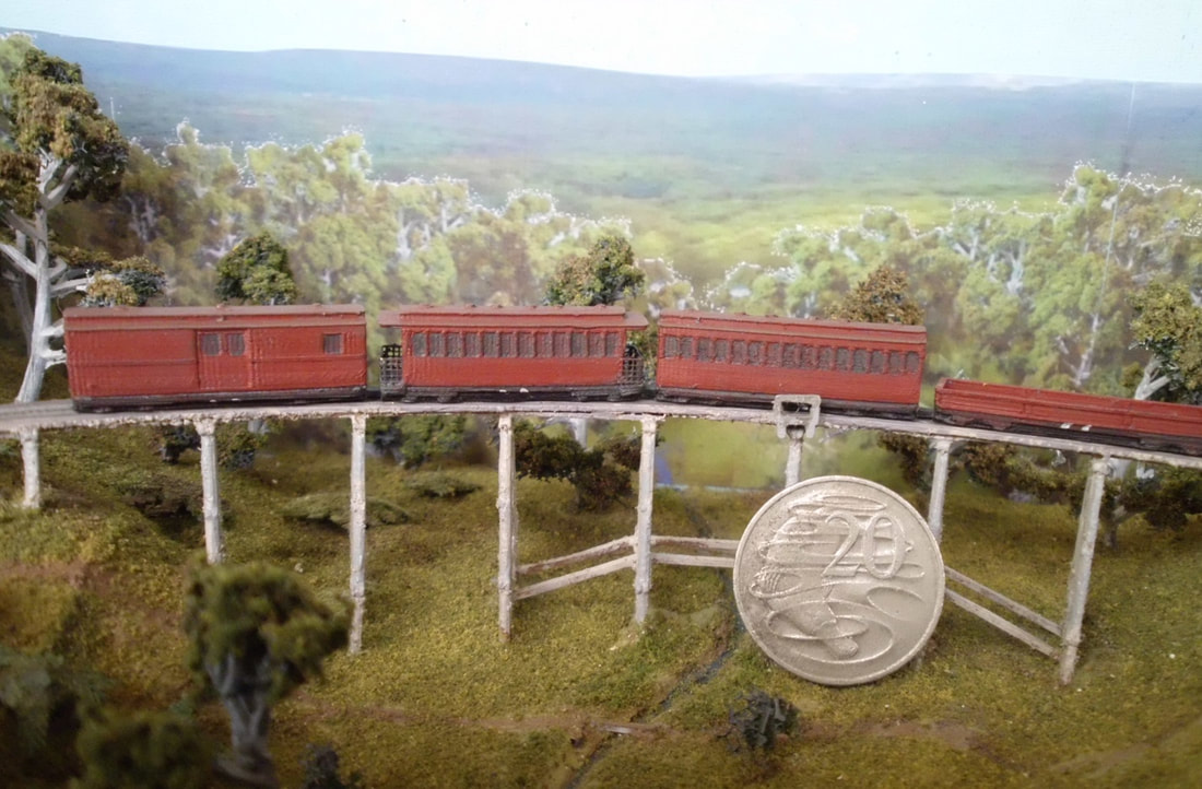 It has been a while since I have built any new trains, so here is the first of a few planned experiments: scaling up the Victorian Railways narrow gauge stock by 60% from 1:350 to 1:220 (Zn30). A few extra details on the 3D prints, a quick paint job, and they look reasonable. They do run, but this is about the maximum practicable size for the linear motor drive.
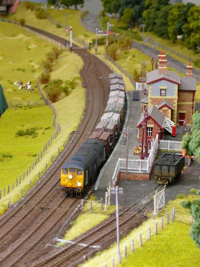
Trains are finally running, so here is a quick work-in-progress video.
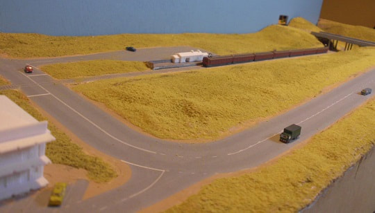
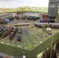
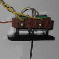
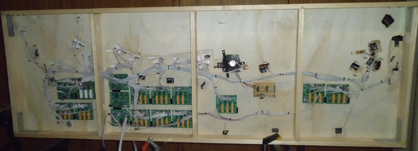 The basic wiring has been completed and tested, the turntable has been installed and tested, and trains are running over the whole layout. It is using a temporary control panel for now, but everything is fully functional.
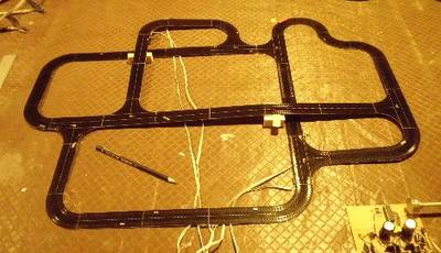
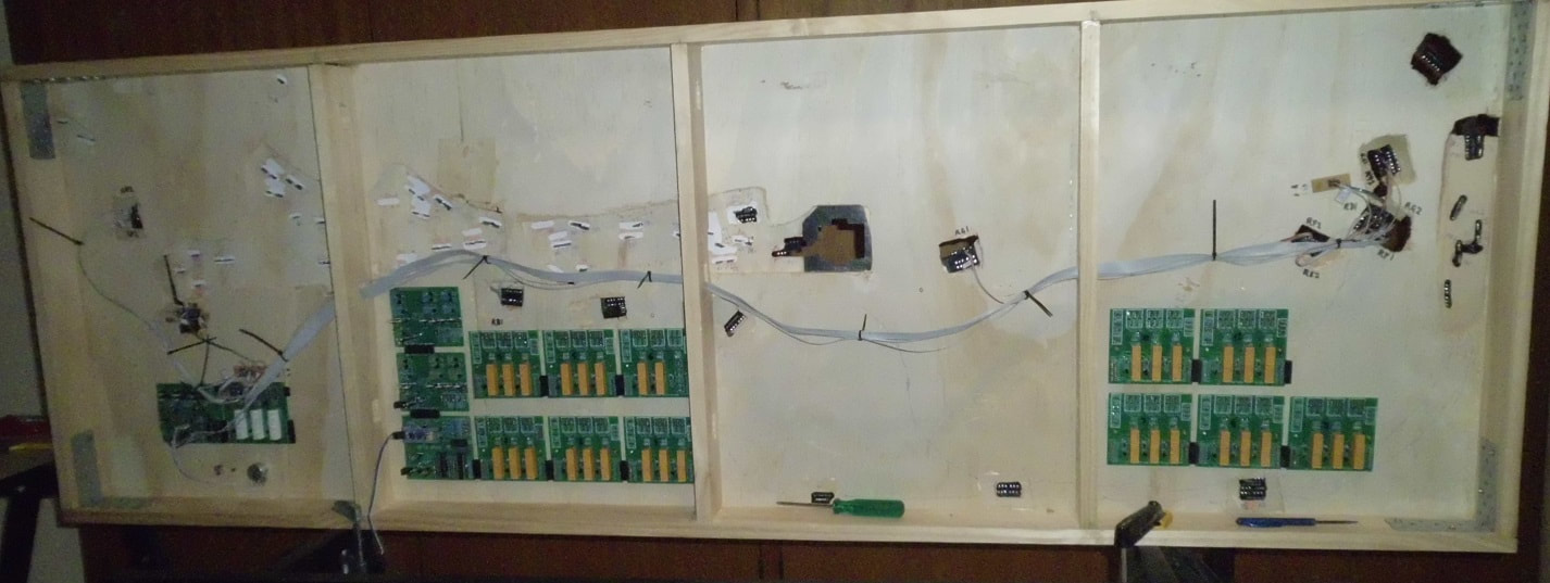 Back on it after a two month break. All the circuit boards are built, tested and provisionally installed, and the road loop is up and running. Next come the 100+ 3-wire cables needed to connect the track to the electronics. I have done this with plug-in connectors at both the track and board ends, so it should be straightforward but tedious.
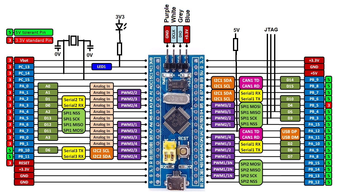 Pinout of Blue Pill board with Annotations (original from os.mbed.com) After posting part 4, I noticed that the serial TX code had a bug that inserted a spurious character occasionally. This part has the fix and adds some simple RX code to complete the USART example. There are many pinout diagrams for the Blue Pill on the web, but the one above is the one I found most useful, originally from the os.mbed.com website. However, several of the board's pins have attached circuitry which limits how they can be used. This version of the diagram has all of these sketched in. This version of the zip file has the complete code with all the examples.
 This part largely completes the set of peripheral libraries needed for the controller, so will probably be the last of this series for while.
The STM32F103 chips don't have any onboard EEPROM, but similar results can be achieved using some of the flash memory. This should have been an easy task, straight from the manual, but they seem to have left out some of the steps. Anyway, I couldn't find them! My project uses two SPI I/O expanders to drive 32 pairs of relays. When I tried to use the SPI interface in polled mode to do this, I ran into problems that I think relate how the NSS pin is assigned on my hardware. The quick-and-dirty bit bashed alternative used to verify the I/O expander behaviour turned out to be fast enough to do the job, so I have left this as the final implementation. 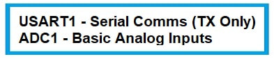 This part expands on the bare bones program, adding basic ADC reads (although only the simplest of several modes), and simple interrupt-based serial comms through a USART. Only the TX side is implemented for now, since this is intended to be used only for debug output. It also does not use DMA buffering, although that would permit faster speeds.
The software assumes that the serial port is on PA9 and PA10, the default pins for USART1, and is wired to a suitable USB-to-serial converter and then handled by a terminal emulator program such as PuTTY. The ADC input assumes that a potentiometer has been attached to PA0 (Analog channel 0), wired across 3V3 and 0V. I use this as the speed control for the trains, cars, canal boats, etc., and as a convenient input during testing (one reason I haven't yet bothered with the USART's RX side). 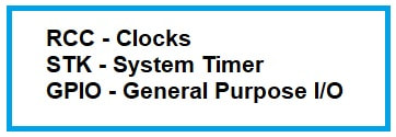 The next few posts will cover how I brought the different hardware subsystems to up and running, including working sample code.
This post covers a very basic RCC, GPIO, and SYSTICK inplementation, and uses them to... blink the LED. The same as the first part, just done my way! Very exciting. |
Overview
British and Australian model railway layouts in T, N and OO. My Layouts
Friends' Layouts
Main Articles
Categories
All
Archives
April 2024
AuthorMartin Kaselis |
||
 RSS Feed
