
This part largely completes the set of peripheral libraries needed for the controller, so will probably be the last of this series for while.
The STM32F103 chips don't have any onboard EEPROM, but similar results can be achieved using some of the flash memory. This should have been an easy task, straight from the manual, but they seem to have left out some of the steps. Anyway, I couldn't find them!
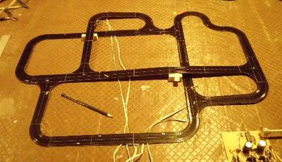
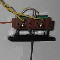
My project uses two SPI I/O expanders to drive 32 pairs of relays. When I tried to use the SPI interface in polled mode to do this, I ran into problems that I think relate how the NSS pin is assigned on my hardware. The quick-and-dirty bit bashed alternative used to verify the I/O expander behaviour turned out to be fast enough to do the job, so I have left this as the final implementation.
The STM32F103 chips don't have any onboard EEPROM, but similar results can be achieved using some of the flash memory. This should have been an easy task, straight from the manual, but they seem to have left out some of the steps. Anyway, I couldn't find them!
My project uses two SPI I/O expanders to drive 32 pairs of relays. When I tried to use the SPI interface in polled mode to do this, I ran into problems that I think relate how the NSS pin is assigned on my hardware. The quick-and-dirty bit bashed alternative used to verify the I/O expander behaviour turned out to be fast enough to do the job, so I have left this as the final implementation.
FLASH - Simulated EEPROM
The STM32F103C8T6 chip has 64K of flash memory arranged as 64x 1K pages. This version of the code sets up the top 1K as a simulated EEPROM.
While the flash can be read as normal memory, it can only be erased to FFs as full 1K pages and only written in 2 byte chunks. There are numerous protection features in the product to prevent inadvertent writes.
I wrote this code as a page-erase function and a matched pair of 4-byte read and write functions, since this corresponds to how I intend to use it in the final application. This can easily be changed to suit other needs.
The basic information on how to write to flash comes from an STM document covering the F10X range (PM0075). All the required steps are clearly laid out, and do work properly - but only for for the first write or erase operation after each reset! After some head banging, I discovered that the various control bits needed to set up the operation have to be manually reset when the job is done.
The final code is straightforward, and simply follows the manual with the extra cleanup steps added. The test code performs a very limited number of writes and erasures after each reset, to avoid the risk of wearing out the flash. I didn't search for the figures for this, but flash is typically limited to 10k erase/write cycles. This is something you ALWAYS need to consider with flash/EEPROM code.
SPI - GPIO Bit Bashing
The STMF103 chips support 4 different ways to implement an SPI interface: the built in SPI hardware plus one of DMA, interrupts, or polling; and simple brute-force bit bashing with GPIO pins.
My project requires writing 4-byte command strings to two I/O expanders a couple of times a second at most. This is not exactly a demanding application, so I intended to use the simplest of the hardware-assisted modes: the built-in SPI peripheral with polling. Unfortunately I ran into problems, probably self-inflicted.
The complications seem to arise from the NSS pin, which is included as a "helpful" feature for some configurations. A quick skim of the manual before designing my boards led me to believe that this pin was completely optional and could be assigned as general I/O, which I promptly did. It turns out that it is not that simple, and I have not yet found a way around the problem. If you use the SPI interface, reserve this pin!
As part of the testing process, I wrote a simple GPIO bit bashing version to check out the hardware and my understanding of the I/O expander's behaviour. That version worked first time, and was fast enough to be suitable as the final version (around 300kHz, or 250us to write to both devices). In the end, I decided to stick with that.
The bit-bashed SPI code is extremely simple, using the same pins as the hardware version plus two otherwise unused pins as chip selects.
The SPI target devices are typical examples of the breed: a pair of MCP23S17 I/O expanders, each with 16 bits of configurable I/O and numerous control registers. While you will almost certainly be looking at something else, the sample code shows one possible way to set up and control that sort of device.
| blue-pill-bare-metal-blog4.zip |


 RSS Feed
