Electronics - Working Level Crossing
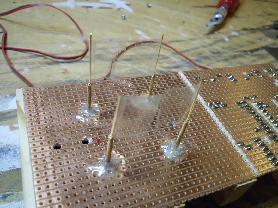
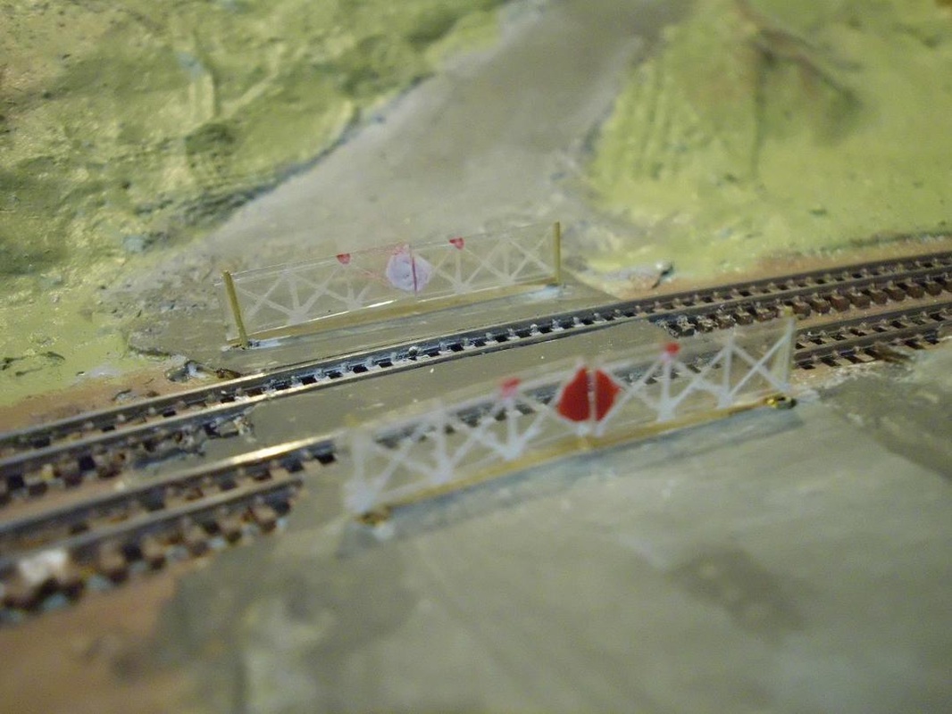
I added a working level crossing to my T gauge layout Sarum Bridge, but the same techniques are equally applicable to larger scales. Because of the small size of T gauge, the gates are made from clear plastic sheet with the framework scribed on then painted. In larger scales, more conventional construction techniques would be better.
|
|
|
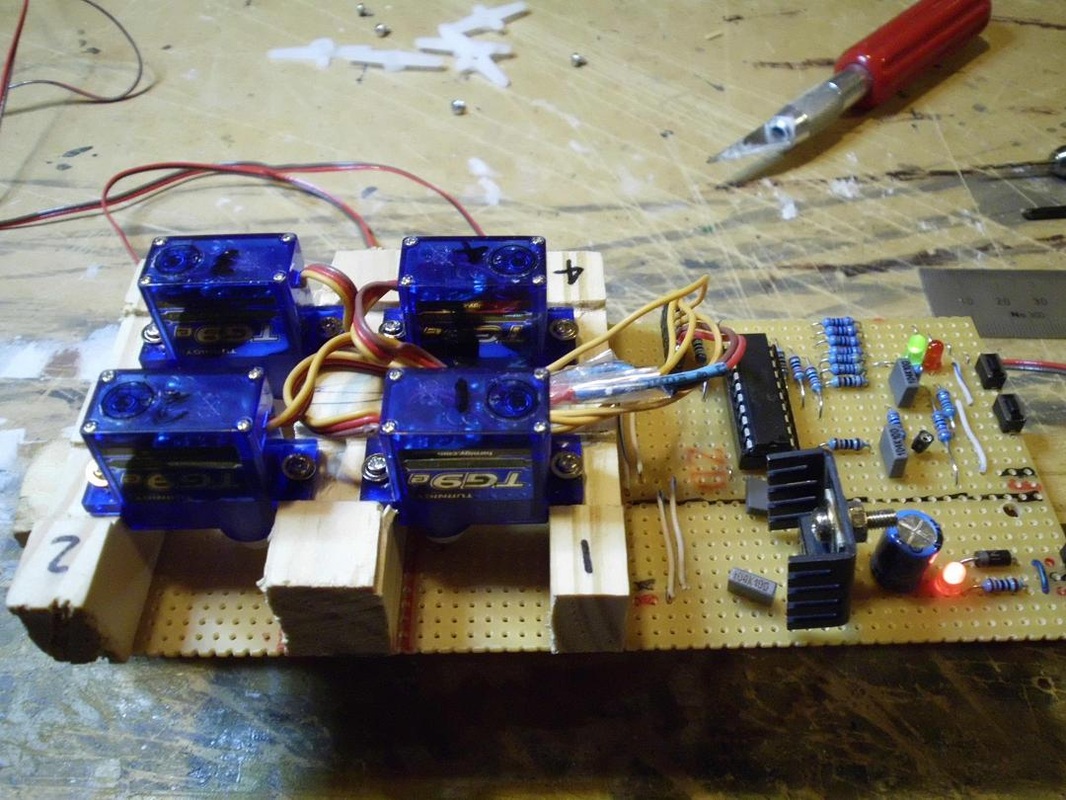
The crossing is the manual type with four gates worked from a signal box. The model is driven by four cheap $3 servos under the board, controlled by a dedicated microcomputer equivalent to (but a lot cheaper than) products produced by a number of manufacturers. Most small micros have the hardware needed to drive up to four servos.
The drive circuitry for a servo is trivial - connect the chip directly to the 4.8V-6V servo control wire through a 1K resistor, and it shares the same 5V power supply as well. As long as there are a couple of capacitors (10uF and 0.1uF) near the chip to keep its voltage stable, everything works fine.
The activation signal is provided by the main automation board for this layout, but hanging 4 LDR or opto sensors off the circuit is also straight forward.
From a software perspective, the only interesting part is sharing the PIC16F690's single PWM channel between 4 different pins to drive the four servos. The position of analog servos is controlled by sending a 1-2ms pulse every 20ms along the control wire to the servo. This particular PIC has a feature known as "pulse steering", that allows the single PWM output to be connected to and shifted between 4 different pins. The software sets the PWM timer for a period of 4ms, then generates a 25%-50% duty cycle PWM pulse. It then shifts the output to to the next pin and sets the new PWM duty cycle, working through all four pins in a round robin fashion. It would have been better to set the timer to 5ms instead of 4, but that was a difficult number to achieve with this particular hardware, so I had to include a 5th dead cycle with no pins enabled to complete the 20ms interval as 5x4ms blocks.
