T Gauge PWM Controller
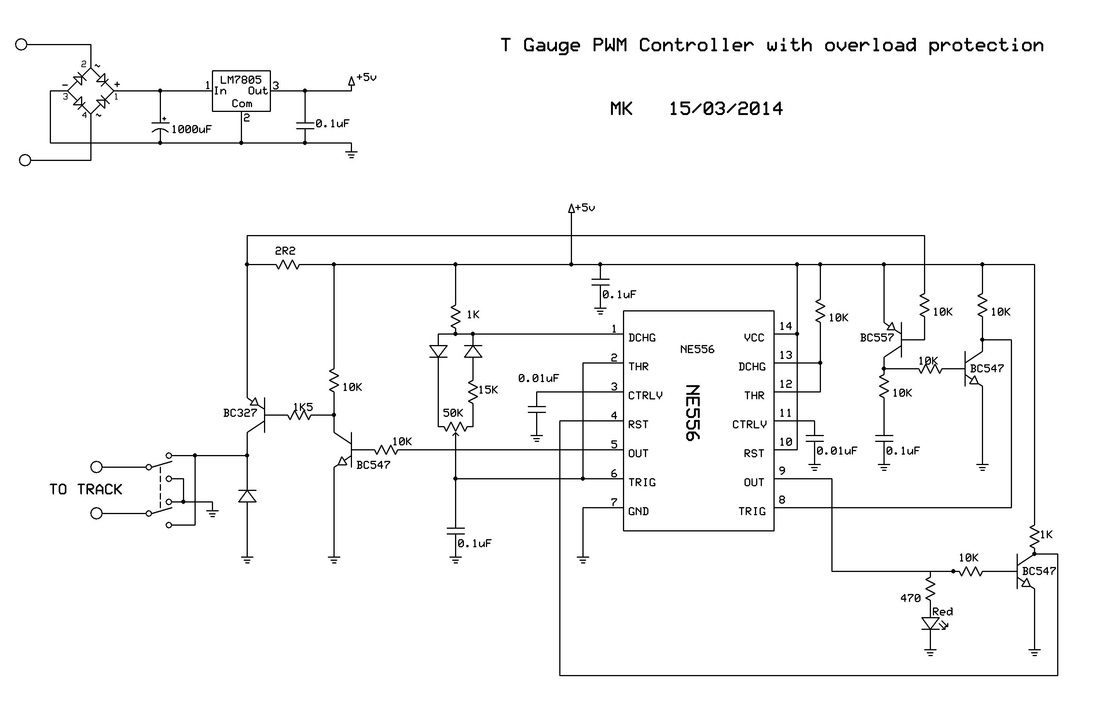
This circuit uses a 555 timer to provide a basic PWM controller for T Gauge models. Its performance is equivalent to the current commercial offering, but also has full overload/short circuit protection (ending up taking more than half the circuit!).
The pulse voltage from this design is just under 5V, but the 15K resistor connected to the potentiometer limits the output to an 80% duty cycle, so the average voltage never exceeds 4V. The pulse frequency is about 180Hz, faster than the commercial product's 100Hz. I feel that this gives slightly better low speed response, but the difference is very marginal. If you do want to match the original frequency, put a 0.047uF or 0.068uF capacitor in parallel with the 0.1uF capacitor at the lower left corner of the circuit.
The basic circuit uses one 555 timer, and the overload circuit requires another, so a 556 dual timer chip is used. You could use two separate 555s if you prefer. Most of the transistors are BC547s and BC557s, but BC548/BC549 and BC558/BC559s or any common NPN/PNP types could be used instead. The exact values of the 10K resistors are not critical, but all other components should use the values as shown. All resistors can be 1/4 watt types.
The 1R5 resistor (originally 2R2), setting the maximum overload current to approximately 400mA, is enough for at least 8 locos. If necessary, you could reduce this resistor value in order to to drive more locos. The overload protection is solid - at the first hint of an overload, the second 555 forces the main PWM 555 timer into reset so that the power pulse is immediately aborted. When the timer comes out of reset, it tries to generate pulses again, and if the short circuit is still there the cycle repeats. A short can be maintained indefinitely with no harm done.
If you don't want the overload circuitry, just use a single 555 and delete everything to the right of the IC (but leave the VCC supply to the IC!). Connect the 555's RST pin to 5V. Omit the 1R5/2R2 resistor and connect the BC327's emitter directly to 5V.
You can further improve the low speed running by slightly raising the peak track voltage from 4.5V to 5.0V or so. Just insert a 1A diode between the middle pin (2) of the 7805 regulator and ground, pointing to ground.