General Tips - B&B Couplings
When I got back into N gauge railway modelling a few years ago, I did a comparison of various types of auto coupler. I tried out Microtrains, DG, Sprat & Winkle and B&B. I ended up choosing B&B as they seemed to provide the best balance between operation, appearance, ease of assembly and ease of installation.
This was obviously a highly subjective decision, and in the end came down to B&B versus Microtrains. The deciding factors were:
This was obviously a highly subjective decision, and in the end came down to B&B versus Microtrains. The deciding factors were:
- the relative ease of installation onto British N stock.
- B&B couplers do not need the awkward "Kaydee shuffle" to release a coupler: the loco just has to keep pushing steadily.
- simple low-power electromagnets can be used.
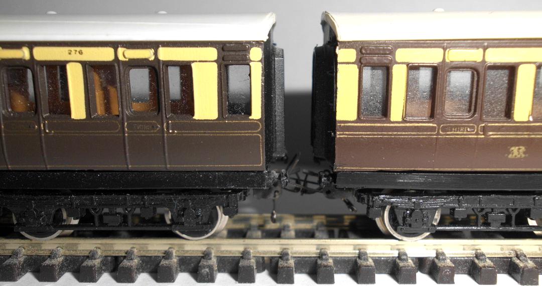
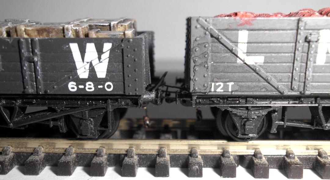
- B&B couplers give a nice "loose coupled" effect with goods trains.
- Microtrains couplers are a very nice knuckle coupler, but Britain never used anything like this. This isn't actually a drawback, but merely the loss of a familiar advantage - Microtrains or Kaydee are still the obvious first choice when modelling US or Australian prototypes on the grounds of appearance alone.
Assembly
Some people seem to have trouble assembling the B&B couplers. Initially, I too found that assembly was unpredictable. Sometimes one would go together perfectly. The next one could take 15 or 20 minutes of struggling to get all the pieces together. I eventually figured out that problem lay in how the side wings were bent down. The bend lines must made be as far out as possible, giving the widest possible coupler. If the bends are made too far in, the holes for the capture latch are too low and you cannot put the latch in place: it goes into one hole but fouls the coupler body. A narrow coupler also makes it hard to insert the latch because you have to temporarily bend the forward flanges out a little. If you bend them far enough to make room for the latch, they are nearly at 45 degrees which effectively makes the holes too small for the pins.
I also find that the couplers work better with a little more iron wire than the instructions recommend - another couple of turns is about right.
I tried using a statically mounted coupler as a test jig, but found that this was too awkward. Instead, I have a reference coupler on a dedicated coach chassis.
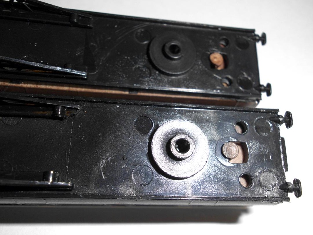
Loops or No Loops
You have the option of making the couplers with or without the loops. Couplers without loops are less conspicuous and often used on locos. However, I found that reliability suffered when doing this: trains tended to uncouple spontaneously.
A bit of investigation showed that the main problem was variations in coupler height. You can never get all your couplers installed at exactly the same height, so there is usually a slight height difference whenever two vehicles are coupled together. If both couplers have loops, then the lower coupler's loop tends to go over the higher coupler's hook and everything works well. If one coupler has no loop, then obviously the other coupler's loop is always used, regardless of height. If this coupler is higher than the loopless coupler, then the loop only just sits over the hook - any bump or track irregularity can cause it to bounce off. Also, if both couplers have loops, the unused loop tends to act as a weight resting on top of the active loop and so helps to keep the vehicles connected.
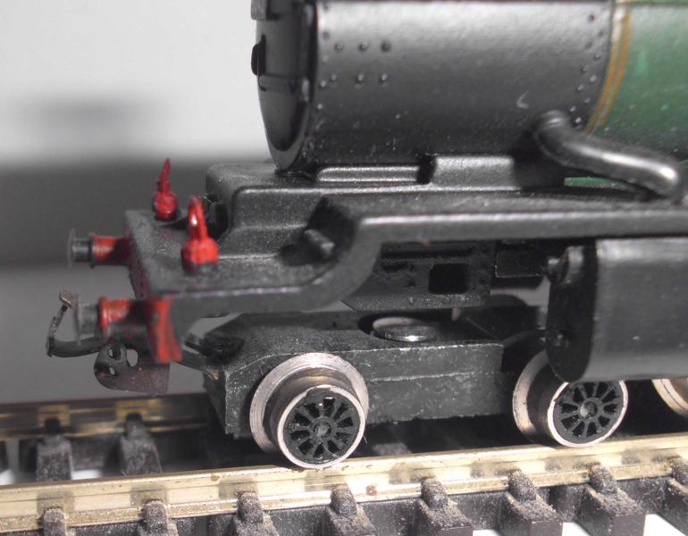
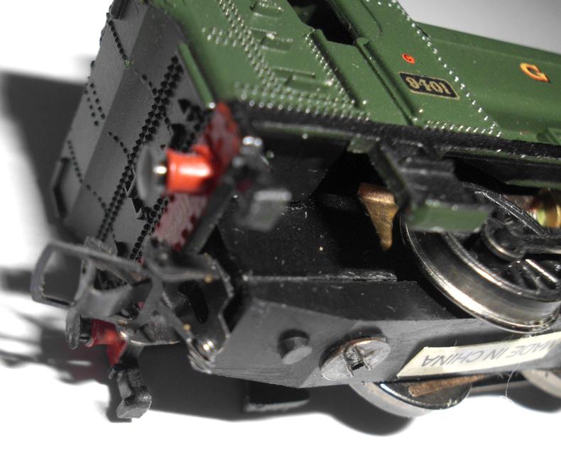
In the end, I chose to use full couplers in all situations except the front couplers of tender locos, and I try to mount these special loopless couplers a little above the standard height.
Installation
TBD
Operation and Adjustment
TBD
Making your own Uncouplers
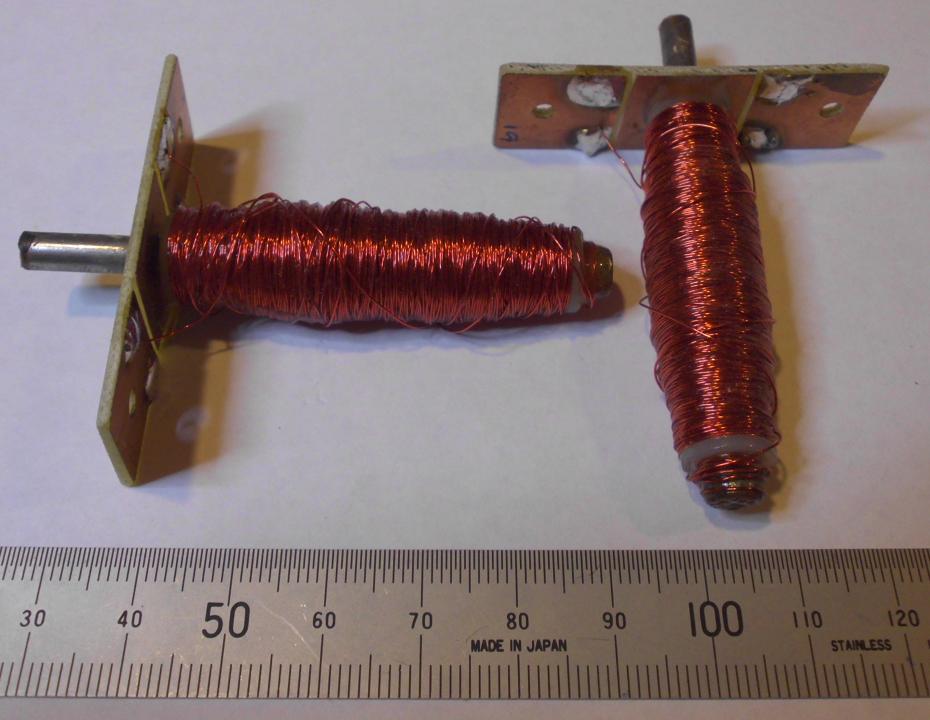
This is a surprisingly simple job. Each uncoupler consists of a four inch nail, a couple of plastic washers or discs (board game tokens), a piece of blank printed circuit board and a complete 25g spool of 0.25mm enameled copper wire.
Put the two disks or washers onto the nail, leaving enough of a gap for the coil of wire. I allow 5 cm with narrow (1cm diameter) washers and 2.5cm for the wider 3cm disks. I glue a layer of paper around the nail to insulate it, using PVA/wood glue. The paper isn't strictly necessary. I drill a small hole or notch in the disk nearest the pointy end of the nail to anchor the wire.
I wind the entire 25g coil of enameled wire onto the nail. I put the end of the nail in a hand drill, and put the drum of wire on a bolt between two pieces of wood to provide some friction. I wear a heavy work glove to hold, guide and tension the wire as it winds onto the nail from between thumb and forefinger. Using the whole spool of wire means that you do not have to count turns. I then seal the coil with PVA/wood glue: just smear it over the wire to hold everything in place.
Finish the uncoupler by pushing it through a piece of blank printed circuit board. This needs a hole for the nail and a couple of holes for mounting screws. Use a saw to break the copper cladding into three regions and then solder the two ends of the wire to the outer regions. The enamel must be scraped off the end of the wire using a fine file or fine sandpaper first. The hole through the PCB should be a tight fit, and more PVA glue helps.
When mounting the uncoupler beneath the track, drill a hole between sleepers or remove one sleeper first. Mark the correct length for the nail and then saw it to the correct length. Depending on where it is to be fitted, I have sometimes filed the end of the nail down to a square sleeper cross-section or even mounted the PCB and uncoupler at a 30 or 45 degree angle to clear tracks below.
To a first approximation, the amount of wire wound onto the uncoupler makes no difference to the strength of the electromagnet. The strength equals the number of turns times the current flowing in the wire. If you wind on twice as many turns, you need twice as much wire with twice the resistance and so half the current. You are trading off the amount of wire (and hence the size and monetary cost) against the current required to operate the uncoupler. In practice, it is not quite that clean and simple: as you wind on more wire the average diameter and hence resistance of each turn increases, so the strength does fall off slightly. It is, however, close enough. I deliberately use a lot of thin wire to keep the power requirements down. This gives a coil with a resistance of 18-20 ohms, requiring about 0.8 amp to operate. This means that normal switches, plugs and light hookup wire can be used, and no special power supply is required.