Electronics - Colour Light Signals, Automation & Interlocking
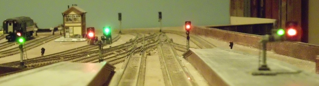
Plymouth Citadel is now (almost) fully signalled using color light signals to a slightly simplified BR pattern. The main line is fully automated using a block system to queue trains with the signals interlocked with the points and station arrival/departure tracks. The station signals are controlled by a simulated interlocked lever frame, so that all movements within the station are controlled by some particular signal. A further planned enhancement will use this signalling to control the cab control logic, so that drivers no longer have to worry about this - just set the points, clear the signals and drive the trains.
This page shows how I implemented the electronics. This could be the basis of a simpler scheme using the LEDs, one or two one-LDR sensors and stop relay circuits and a cut-down version of the software. This would be the equivalent of a typical commercial signalling module. The Plymouth Citadel Signals page shows how I built the signals themselves and the results, including video.
This page shows how I implemented the electronics. This could be the basis of a simpler scheme using the LEDs, one or two one-LDR sensors and stop relay circuits and a cut-down version of the software. This would be the equivalent of a typical commercial signalling module. The Plymouth Citadel Signals page shows how I built the signals themselves and the results, including video.
The Main Line Signals and Automation
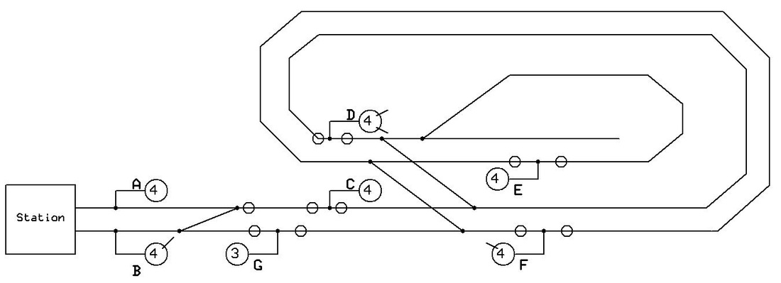
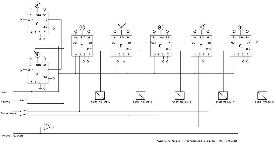
There are seven main line signals: six 4-aspect and one 3-aspect. Three of these have junction feathers (one with two feathers), and each has an associated stop section for automatic train control. I use LDRs (light dependent resistors) as sensors. Each signal is controlled by a separate PIC microcontroller, running identical firmware. Each PIC communicates with its neighbours using 2kHz variable-duty-cycle pulses. There are also extra inputs for interlocking with the point relays and the station arrival switch.
Basic model railway colour light signal automation is normally quite simple. In its commonest form, each signal needs a momentary sensor immediately after it, and a relay-operated dead section immediately before it. I chose to complicate the situation significantly to allow for double heading, multiple-unit and push-pull trains, especially important with an out-and-back track plan. This requires an extra sensor in front of each signal, capable of detecting both moving or stationary trains, which causes the power to be cut from the entire block section so that the train stops whether its locomotive is at the front or the back. This also makes setting the signal to red more difficult, since when the leading vehicle passes the sensor after the signal, the loco could still be back in the main section. I solve the problem in software by having two distinct red states: armed and not armed. The signal goes red when the trailing sensor is passed, but does not actually arm the stop logic until the leading sensor is clear again.
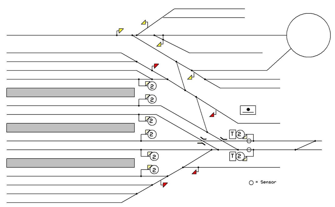
The normal operating mode for the main line is as a long out-and-back loop, with 5 blocks each controlled by a signal. The two signals controlling entry to the main line from the station area also have stop blocks to avoid operators overrunning the signals and messing up the automation. These stop blocks have diodes so that shunting moves are protected, but trains can then back away again. The double sensors are required here too since the loco can be anywhere in the train when shunting.
There are two crossovers that convert the out-and-back into a double track continuous run. Each of these ovals has only one signal, which operates in a simple timed mode so that it appears to be part of a longer sequence of signals. When a train passes the signal, it goes red. Then, over the next 16 seconds, it works its way back through the various aspects to green. The timed/crossover mode also activates the appropriate junction feather. This mode is also interlocked with the neighbouring signals to prevent collisions. The points can be changed back and forth at any time (as long as there is no train actually on them!), so when switched back the timed mode continues until the train gets back to the signal.
There are seven main line signals: six 4-aspect and one 3-aspect. Three of these have junction feathers (one with two feathers), and each has an associated stop section for automatic train control. I use LDRs (light dependent resistors) as sensors. Each signal is controlled by a separate PIC microcontroller, running identical firmware. Each PIC communicates with its neighbours using 2kHz variable-duty-cycle pulses. There are also extra inputs for interlocking with the point relays and the station arrival switch.
Basic model railway colour light signal automation is normally quite simple. In its commonest form, each signal needs a momentary sensor immediately after it, and a relay-operated dead section immediately before it. I chose to complicate the situation significantly to allow for double heading, multiple-unit and push-pull trains, especially important with an out-and-back track plan. This requires an extra sensor in front of each signal, capable of detecting both moving or stationary trains, which causes the power to be cut from the entire block section so that the train stops whether its locomotive is at the front or the back. This also makes setting the signal to red more difficult, since when the leading vehicle passes the sensor after the signal, the loco could still be back in the main section. I solve the problem in software by having two distinct red states: armed and not armed. The signal goes red when the trailing sensor is passed, but does not actually arm the stop logic until the leading sensor is clear again.
The normal operating mode for the main line is as a long out-and-back loop, with 5 blocks each controlled by a signal. The two signals controlling entry to the main line from the station area also have stop blocks to avoid operators overrunning the signals and messing up the automation. These stop blocks have diodes so that shunting moves are protected, but trains can then back away again. The double sensors are required here too since the loco can be anywhere in the train when shunting.
There are two crossovers that convert the out-and-back into a double track continuous run. Each of these ovals has only one signal, which operates in a simple timed mode so that it appears to be part of a longer sequence of signals. When a train passes the signal, it goes red. Then, over the next 16 seconds, it works its way back through the various aspects to green. The timed/crossover mode also activates the appropriate junction feather. This mode is also interlocked with the neighbouring signals to prevent collisions. The points can be changed back and forth at any time (as long as there is no train actually on them!), so when switched back the timed mode continues until the train gets back to the signal.

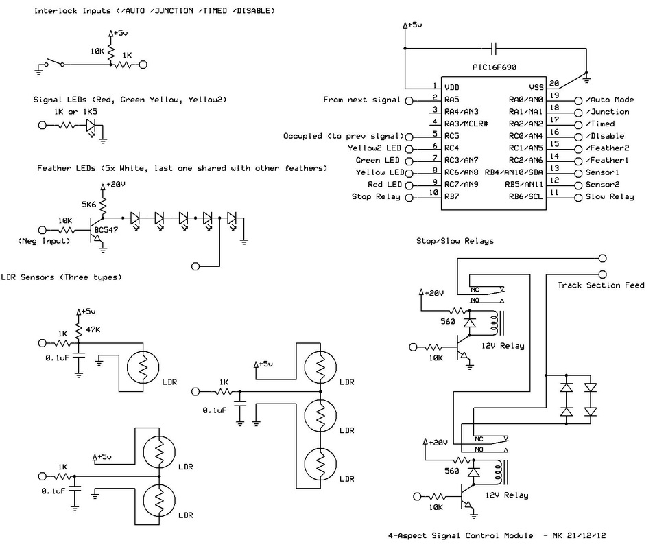
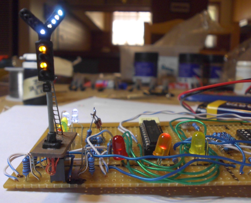
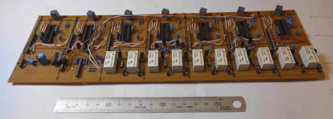
The main signal LEDs are driven directly from the PIC, but the junction feathers consist of 5 white LEDs in series. This gives a more even brightness than trying to wire them in parallel, but requires a supply of at least 18V. I chose to do it this way since the layout already has a smoothed 21V DC supply for the points.
The stop and slowdown relay wiring is straightforward, although the slowdown circuit ended up being useless to me since the feedback controllers I use do a painfully good job of compensating for the slowdown. Sigh. These will come into play again with a planned future enhancement.
I chose to use simple LDRs with no extra light source. Each is connected to an analog input of the PIC, which measures the voltage across a resistor divider containing the LDR. There are a couple of tricks here to avoid having to calibrate each sensor and to allow them to adapt to various lighting conditions. The sensors immediately after each signal use a single LDR to detect a passing train. I merely look for a sudden darkening, so these will work under any (reasonable) lighting conditions. The sensors in front of each signal have to be able to detect the presence of both moving and stationary trains. The basic solution is to use a balanced pair of LDRs, one between the rails and the other beside them. Under normal conditions, they each receive the same amount of light and so have the same resistance, giving a test point voltage of around 2.5V. When a train blocks the light, the balance shifts. In practice I had to use three LDRs per sensor, since it is possible for a train to stop with a coupler over the sensor, which may not create a sufficiently dark shadow. The LDRs are then placed half a wagon length apart. It is possible to get spurious detections if I lean over the layout or move rolling stock around by hand, but in practice this is not a serious problem. The circuit board includes deglitch capacitors for each sensor, since model railways are electrically noisy environments.
Note that the triple-LDR sensors were originally installed for a simpler relay-based automation system, and I have chosen to retain them even though I could have reverted to using a single-LDR sensor using the second single-LDR sensor as the ambient light reference.
I chose to use the PIC16F690 from Microchip's medium-speed range, obviously because it was adequate for the job with a good number of I/O pins, but also because it was the sample chip supplied with Microchip's PicKit2 programming unit. I have elected to standardize on this device for all low- to medium-end tasks. It is a 20-pin 5V device, with 18 usable I/O pins. Most can be analog inputs, and there is one PWM output. I used the free (Lite) version of the Hitech C compiler available from the Microchip website.
The program doesn't do anything fancy, using the default clock settings and not bothering to enable interrupts. It is basically a processing loop that executes every 100ms, reading all inputs, deciding what to do, then writing all outputs. The only tricky bit is communicating between signal units. I originally had three simple inputs connected to the next three signals in advance, but this was not capable of handling all the weird interlock cases involving junctions, etc. Each signal controller now has one input that provides the combined state of all signals up the line, and generates a similar output. This basically tells the previous signal what aspect to display (red, yellow, yellow2 or green), although each signal can always choose to set a more restrictive aspect. This output uses the PWM hardware to generate a variable duty-cycle 2kHz pulse train. 100% for red, 75% for yellow, 25% for yellow2 and 0% for green. This value can be sampled by a simple poll loop with counter, taking 1-2ms to determine a result.
The automation is designed to start up correctly if all trains are correctly stopped in front of their signals when the power is turned on. As a result, shutting down simply requires waiting until all trains have stopped moving before turning off the power. Cycling the auto switch off then on has the same effect.
Any automation or computer system needs some sort of reset mode . There is a switch to turn automation on or off. When off, the signals work normally but the stop relays are disabled (except those tied to the ~disable input protecting trailing points). Whenever this switch is moved, all memory states are cleared. The system correctly handles all normal situations, but major derailments or manual intervention can cause trouble.
I have provided the source code for anyone interested. Free for non-commercial use. No warranty!
| sigmain.c |
The Station Signals and Simulated Lever Frame
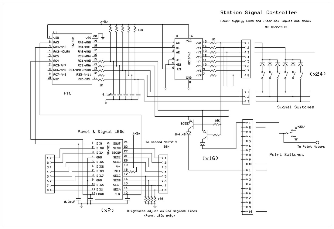
A single PIC16F690 PIC microcontroller handles all the signalling work for the entire station. The code occupies 2K of the 4K flash (even with the HiTech C compiler running in its free no-optimisation mode), but all 256 bytes of EEPROM are used for the interlocking and LED tables.
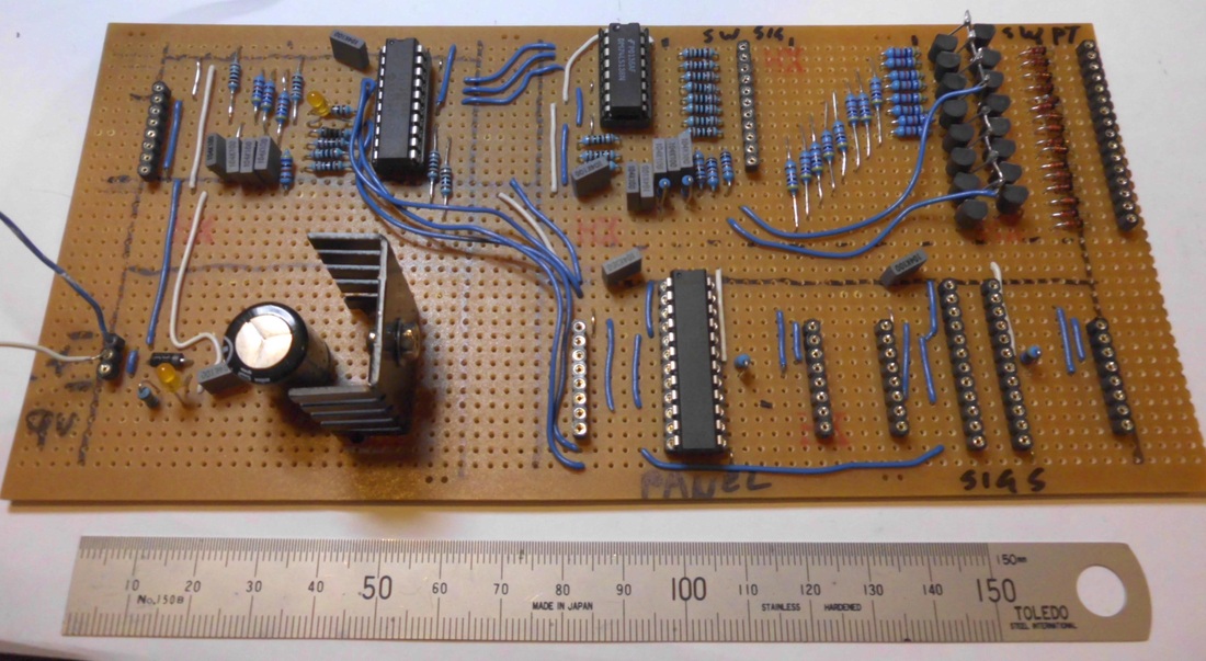
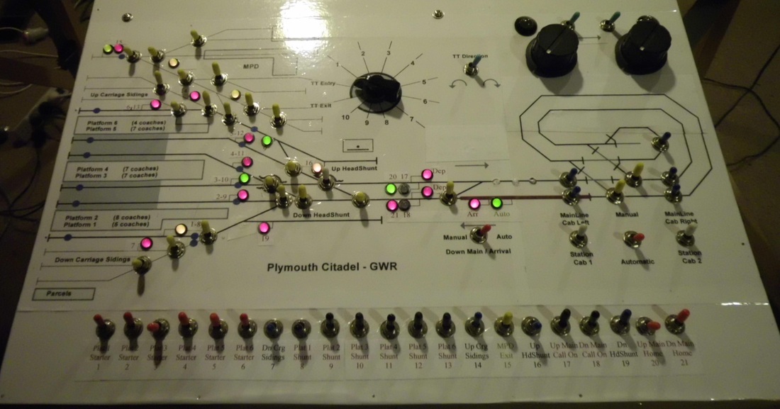
The main panel has a bank of 21 toggle switches configured as a partial (signals-only) lever frame and a full set of bi-colour repeater LEDs for the signals (set up as red=danger,yellow=shunt, green=running signal). Unfortunately these were chosen and installed for my original semaphore-based signalling scheme, so their arrangement doesn't quite match the final colour-light design.
A conventional 8x3 switch-scanning matrix is used to read the lever frame toggle switches, using a 74LS138 to drive the scan, and so requires 3 bits for output and 3 more for input. With some extra input circuitry, this handles the point switches as well. The point switches connect a smoothed 20V or 0V to each point motor control circuit, so are fairly easy to monitor (except for keeping the 20V away from the ICs). The state of each point switch is sensed by a transistor/diode pair, driven from the same 74LS138. This requires the use of 2 more input bits. Only 16 of the 21 points or crossovers in the station are sampled - the other 5 are deep within the MPD and carriage sidings, so have no effect on the interlocking.
The signals and points are fully interlocked, except there is no attempt to restrict point operation. The interlocking is set up to check for correct the point settings and no conflicting signals. If the points are changed under an active route, the signal goes back to danger. Two of the single-LDR sensor circuits are used to reset the signals as trains pass through the main tracks of the station throat.
The signal and panel repeater LEDs are driven by a pair of MAX7219 LED driver chips, one for the panel and one for the signals. Each can handle 64 LEDs, and the drive current can be set so that few resistors are needed. In theory no resistors should be required, but brightness balancing issues between the various LED colours means that it is not quite that simple. The red on the bicolor LEDs on the panel is much brighter than the green, which looks odd enough even when only displaying these two colours. The combination of red and green gives a deep orange which is hard to distinguish from red. Putting a 150 ohm resistor between each of the four red segment drive outputs and ground balances things out nicely. Two chips are required, partly because the total number of signal and panel LEDs is 88 rather than 64, and partly to simplify the brightness problem: the signal and panel LEDs need very different current settings. It also allows optimization of the data tables in memory - the LEDs for each signal switch are wired to fit into at most one nibble each for the signal and panel LEDs
The main difficulty for the software was squeezing the interlocking and LED data tables into the limited EEPROM space of the PIC. I just barely managed it, but some could have been moved out into flash if necessary. Code size is just 2K out of the available 4K (even with the HiTech C compiler running in its no-optimization mode).
This design is a specialized solution for a particular situation. The signal switch and LED electronics and basic interlocking code are reasonably general, but the specifics and point handling are probably of more limited interest.
A single PIC16F690 PIC microcontroller handles all the signalling work for the entire station. The code occupies 2K of the 4K flash (even with the HiTech C compiler running in its free no-optimisation mode), but all 256 bytes of EEPROM are used for the interlocking and LED tables.
The main panel has a bank of 21 toggle switches configured as a partial (signals-only) lever frame and a full set of bi-colour repeater LEDs for the signals (set up as red=danger,yellow=shunt, green=running signal). Unfortunately these were chosen and installed for my original semaphore-based signalling scheme, so their arrangement doesn't quite match the final colour-light design.
A conventional 8x3 switch-scanning matrix is used to read the lever frame toggle switches, using a 74LS138 to drive the scan, and so requires 3 bits for output and 3 more for input. With some extra input circuitry, this handles the point switches as well. The point switches connect a smoothed 20V or 0V to each point motor control circuit, so are fairly easy to monitor (except for keeping the 20V away from the ICs). The state of each point switch is sensed by a transistor/diode pair, driven from the same 74LS138. This requires the use of 2 more input bits. Only 16 of the 21 points or crossovers in the station are sampled - the other 5 are deep within the MPD and carriage sidings, so have no effect on the interlocking.
The signals and points are fully interlocked, except there is no attempt to restrict point operation. The interlocking is set up to check for correct the point settings and no conflicting signals. If the points are changed under an active route, the signal goes back to danger. Two of the single-LDR sensor circuits are used to reset the signals as trains pass through the main tracks of the station throat.
The signal and panel repeater LEDs are driven by a pair of MAX7219 LED driver chips, one for the panel and one for the signals. Each can handle 64 LEDs, and the drive current can be set so that few resistors are needed. In theory no resistors should be required, but brightness balancing issues between the various LED colours means that it is not quite that simple. The red on the bicolor LEDs on the panel is much brighter than the green, which looks odd enough even when only displaying these two colours. The combination of red and green gives a deep orange which is hard to distinguish from red. Putting a 150 ohm resistor between each of the four red segment drive outputs and ground balances things out nicely. Two chips are required, partly because the total number of signal and panel LEDs is 88 rather than 64, and partly to simplify the brightness problem: the signal and panel LEDs need very different current settings. It also allows optimization of the data tables in memory - the LEDs for each signal switch are wired to fit into at most one nibble each for the signal and panel LEDs
The main difficulty for the software was squeezing the interlocking and LED data tables into the limited EEPROM space of the PIC. I just barely managed it, but some could have been moved out into flash if necessary. Code size is just 2K out of the available 4K (even with the HiTech C compiler running in its no-optimization mode).
This design is a specialized solution for a particular situation. The signal switch and LED electronics and basic interlocking code are reasonably general, but the specifics and point handling are probably of more limited interest.
The Interlocking Software
The software is designed as a simple processing loop taking around 100ms per cycle. I use the default clock settings and don't enable interrupts, so the timing is approximate.
Each 100ms cycle is broken into 9 substeps each of around 10ms duration (the ninth takes more like 20ms). The first eight substeps each read one row (5 bits) of switch data, then set the 74LS138 to the next required value and leave time to let the debounce capacitors settle. Each MAX7219 holds 8 bytes of LED data, so one byte of saved data is written to each chip during each of these 8 substeps. ADC reads are also spread amongst the 8 substeps.
All the heavy processing is combined into the ninth double-length substep at the end of each 100ms cycle. The basic concept is to have two copies of the switch settings: the actual position of the switches, and the validated position of the corresponding interlocked levers. Ideally, these have the same value, but the levers can be forced back to red regardless of the position of the actual switch. The operator and the interlocking have to agree in order to set a signal to green. The signals and panel repeaters are always driven based on the validated positions.
The interlocking data is stored as a list of 8-byte route descriptors. Each route contains a 2-byte mask for which points are involved, and another 2 bytes for the actual settings of these points. There is also a 3-byte signal switch bit vector specifying what signals control this route. Most routes have four signals: a running signal and shunt signal pair from each end of the route. There is also 1 byte with extra flags and indicating what cab control section is needed for this route. The basic interlock processing verifies that a switch newly moved to the green position is valid by searching the route table until it finds a route that uses this signal and which matches the current point settings. If none is found, or if any of the other signals for that route are already set, then the attempted switch pull is considered invalid. The cancelling optos are treated as two more signal switches that come on for one processing cycle.
The LED data is stored as a 16-byte bit vector giving the danger state of all 128 possible LEDs (signal and panel). Each of the 21 signal switches has 2 bytes of encoded changes to this vector that are used when this switch is green. Each byte gives a nibble number and a 4-bit XOR mask, one byte each for the panel and signal MAX7219s.
The basic processing at the end of each 100ms goes as follows: all existing green signals are reverified, just in case the points have been changed or a cancelling opto has triggered. Then, all new attempts to set a switch/signal to green are checked, and forced back to red if something is not right. This leaves a bit vector containing all switches that are correctly at green. A default bit vector for the LEDs is then copied into a RAM array - this has every signal and repeater in its red or danger state. For each signal that is green, another table lookup gives two nibbles of data to XOR into this vector: one for the signal itself and one for the panel repeater. A few special cases are then checked, with possible further changes to the LED vector. The final LED vector is written to the LEDs one byte at a time during the next switch scan cycle.
Special cases that are handled in an ad-hoc manner are: the cancelling optos get treated as momentary conflicting signals; the states of the three neighbouring main line signals are used to update some of the panel repeater LEDs; the arrival switch is scanned as a 22nd signal switch and if set cancels any opposing route; and three of the MPD yellow/green ground signals are worked automatically from the point settings.
The unit also transmits a status packet out on the serial port every 100ms, giving the state of all the signals and points, as well as what cab control section is involved. This is intended to be used by a future enhancement to completely automate the layout's cab-control switching.
| sig2main.c |
