Electronics - Working Roads
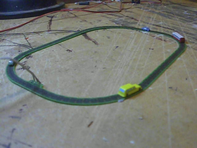
I came across an interesting tiny magnetic-drive linear motor model road product by a company called IDL Motors (www.teenytrains.com). The basic product is just an oval about 6.5" x 4.5" with a number of cars and buses going round and round. The buses are pretty much to scale for T, but the cars are a fair bit oversize.
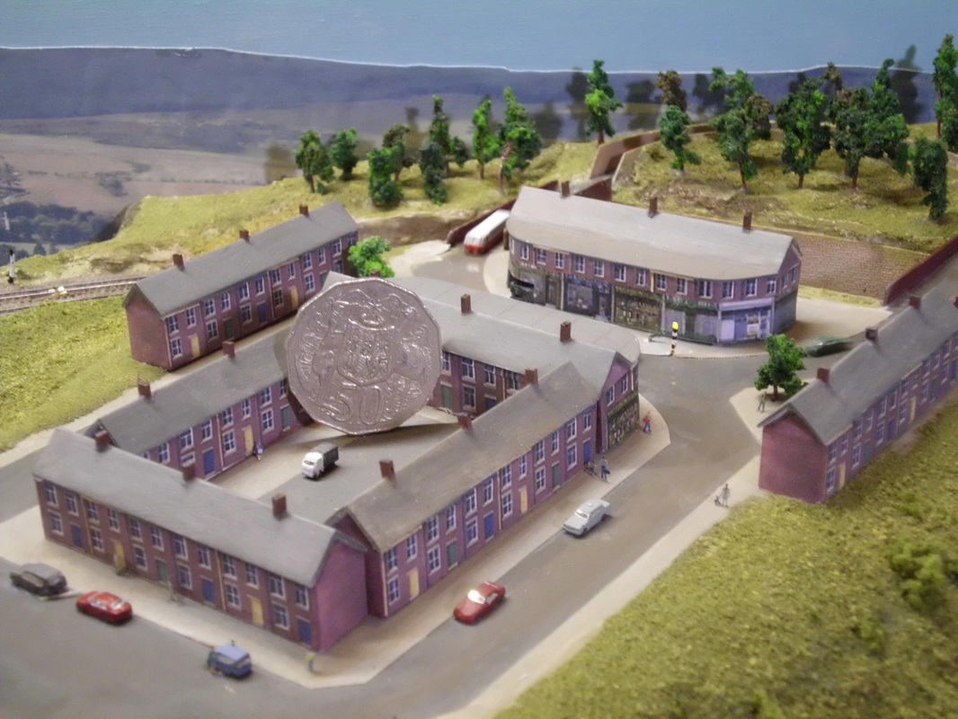
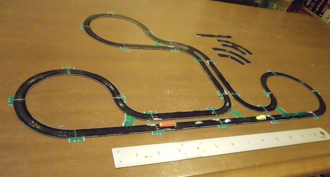
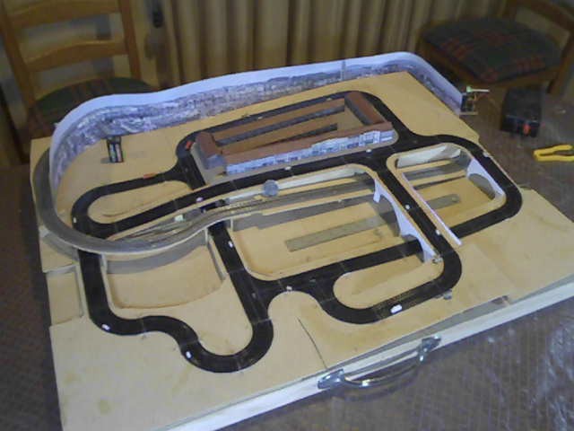
I bought the basic set along with an extra track and more vehicles, and started trying various things. With a bit of work, I ended up with a figure-8 track with vehicles randomly switching from one track to the other. With a bit more work to add a queue (basically a storage track), I had enough to simulate a busy one-way stretch of main road passing a small English village, with the odd vehicle driving into the village. Just enough to fill an otherwise quiet corner of Sarum Bridge.
I bought the basic set along with an extra track and more vehicles, and started trying various things. With a bit of work, I ended up with a figure-8 track with vehicles randomly switching from one track to the other. With a bit more work to add a queue (basically a storage track), I had enough to simulate a busy one-way stretch of main road passing a small English village, with the odd vehicle driving into the village. Just enough to fill an otherwise quiet corner of Sarum Bridge.
I am also slowly working towards having my own sectional track road system for complex T/Z layouts, and hopefully for N as well. This involves designing and making printed circuit boards with the required coils for each track section.

|
|
|
|
|
|
|
|
|
How It Works
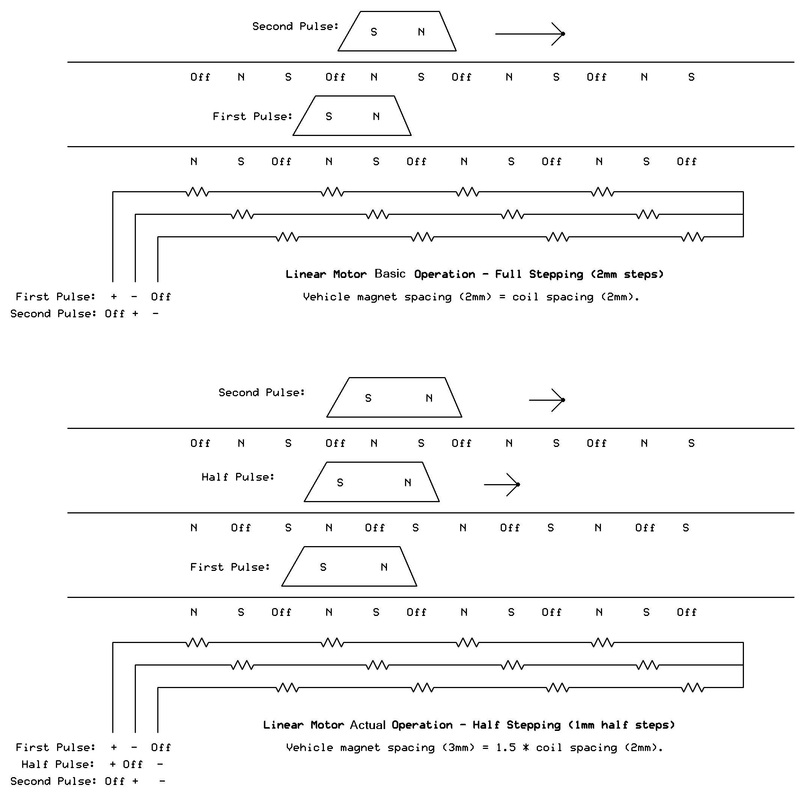
The linear motor track is made up of three interleaved strings of coils (electromagnets). These are all connected together at one end, while at the other end the three wires go to the control electronics. At any time, one wire is driven to a positive voltage, another to zero volts, and the third is simply off. This means that there is always a repeating pattern of three magnets along the track: North, South and Off.
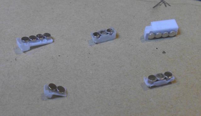
The vehicles have two (or more) magnets on their underside, with alternating South and North Poles. These are attracted to and sit above whichever two coils are generating North and South. The control electronics then switches the +ve, 0 and off states to a different set of wires, effectively moving the N/S/Off pattern further along the track so the vehicle jumps to the new position.
The coils are spaced on 2mm centres (the coils are actually 4mm wide, but alternate on the top and bottom sides of the PCB to halve the spacing). If the vehicles had the same 2mm magnet spacing as the coils, they would jump along by 2mm steps whenever the pattern changed.
The magnets are actually spaced at 1.5 x the coil spacing (3mm), so that they do not quite line up with the coils. This allows a technique known as half-stepping to be used, so the vehicles actually jump 1mm at a time giving a smoother motion.
My version of the drive software goes a bit further and uses another technique known as microstepping. From what was described above, a half step might go from state A (N/S/Off) to state B (N/Off/S). The driver outputs are rapidly swapped back and forth between A and B in varying proportions to generate 3 intermediate sub-steps, in effect making the S pole gradually move from one position to another. The A/B ratios are 100/0 ->75/25 ->50/50 ->25/75 ->0/100. This means that the vehicles advance 0.25mm at a time, giving much smoother low speed running.
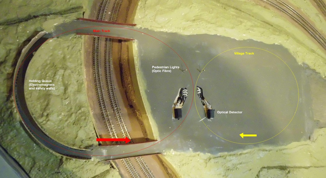
Use on Sarum Bridge
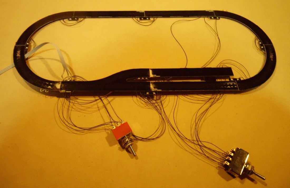
The product comes with a control unit that generates the drive pulses; I added some extra hardware and a PIC microcontroller to handle the more advanced features.
The extra hardware consists of two pairs of relays to switch power to the two tracks (each track has three wires and I use 2-pole relays). Each track draws about 0.3A, and the control box is powerful enough to run drive two tracks. There is a photo interrupter just before the intersection to detect the vehicles. The holding queue is just three electromagnets under the road (cannibalised relay coils) that grab and hold a passing vehicle when turned on, along with a safety wall to stop the vehicles trying to leap sideways off the track when the magnets are powered.
The basic principles of the control system are simple, but there were a lot of fiddly things to get right:
- The road surface material has to be less than 1mm thick, and since the tracks themselves are about 0.5mm thick that doesn't leave much to work with at the intersection. I ended up using very thin clear styrene sheet (0.13mm), and painted it on the underside. I painted in a stop line, and now wish I had added more markings - too late to change it now.
- Everything is synchronised to the drive pulses going to the track. I use this as a master clock and all events and movements are timed from this.
- For the intersection to work, the track power has to be switched at just the right moment to deflect a vehicle. I count a certain number of drive pulses after something passes the optical detector.
- Merging back at the intersection is easy - even with both tracks powered, vehicles just fit back into the flow. Of course, collision avoidance logic helps!
- The relative alignment of the tracks (and their drive coils) at the intersection has to be just right so that vehicles don't slew sideways or leap forwards or backwards - trial and error used here.
- The holding coils have to be far enough apart so that vehicles don't get too close to each other - if they do, their magnets pull them together into a single lump. Mass pile-ups are impressive! The buses are long enough that the electromagnet can grab them by either the front or the back, so need much more space than the smaller cars.
- The holding coils have to be far enough below the track that the vehicles' magnets are not affected by the iron core of the coils. The buses have more powerful magnets, so these are the limiting case.
Vehicles are tracked by counting pulses and using dead reckoning. Each time the opto detects something, a vehicle pulse counter is started. Given the way I monitor the pulses, it takes 77 of them for a complete circuit of a track. The intersection, bus stop, holding coils, etc. are all activated at specific counts. When the count finally reaches 77, the vehicle counter is cleared and that vehicle ceases to exist. If everything has gone correctly, it just happens to be passing the opto at this moment and a new vehicle is created. This allows the software to be adaptable to cope with vehicles being added and removed at will.
Ongoing Experiments
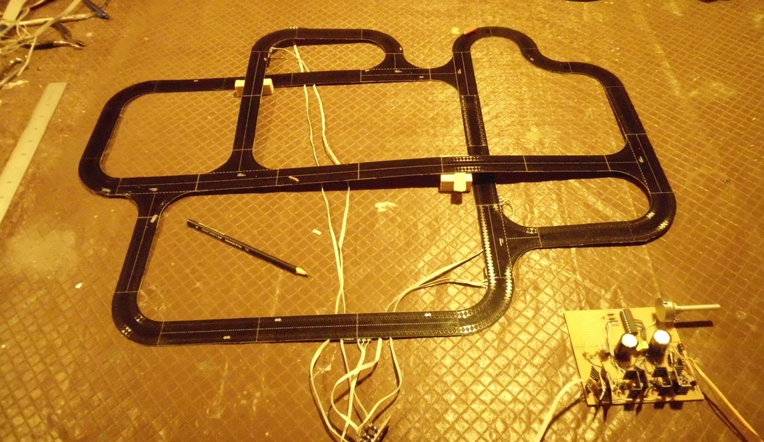
I have built my own drive electronics - basically just what would be a 3-pole stepper motor driver rigged up as a train-set style controller. This lets me control direction and speed, down to shunting speeds, and also gets around from the 6 volt limitation of IDL's unit. That unit is sized to power two 18" tracks (the 6V generates the needed 0.3A for each). I am looking to build a larger track, and a higher voltage would allow much longer sections (around 3' for 12V and 4' for 15V).
The other basic experiment is to find a better way to pause vehicles. The holding magnets used on Sarum Bridge do work, but they impose minimum size and weight restrictions on the vehicles. When I fitted magnets to the smallest Eishindo cars, they ran OK on the basic track but spun around or somersaulted when grabbed by a holding magnet. The new approach is to cut power to a short section of track. Unfortunately, this cannot be done by simply isolating a section. Instead, three lengths of coils need to be short circuited and bypassed using a switch or relay(s). This approach seems to work well, and I intend to use it for road holding queues, sidings and other rail isolating sections, and for implementing points.
I have also started experimenting with trains, both IDL's abstract 1:700 models and proper T gauge designs. Bogie body shells, both 3D printed and the Eishindo types, seem to fit perfectly over IDL's model buses! I will look at some sort of proper chassis and underframe in the future. The objective is a fully functional T Gauge layout using linear motor tracks rather than the Eishindo mechanisms. The potential payoff is a fully functional layout (even to automatic hands-off shunting) and integrated road/rail (level crossings).
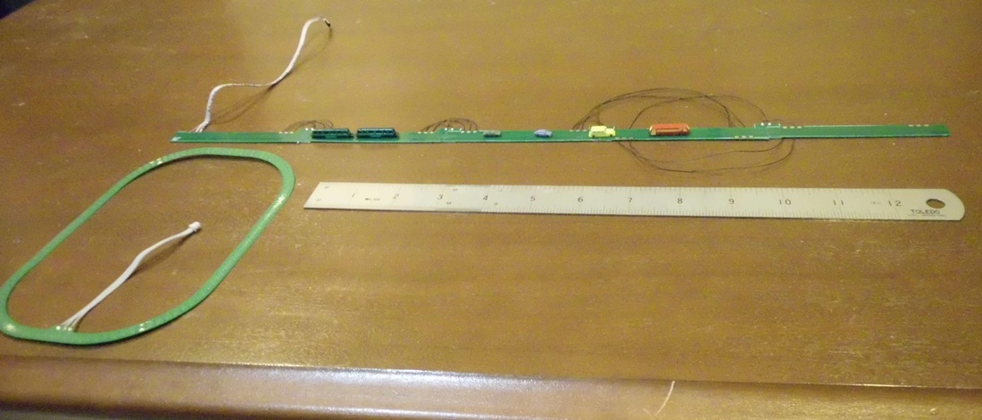
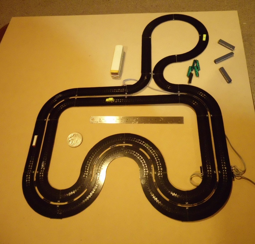
Sectional Track
I am also working on a sectional track system for use on future layouts. This is based on IDL's design but optimised for modelling applications. The current (second) version works well enough for T and Z, but is not powerful enough for N. The track sections are thin double-sided PCBs, with the sections soldered together along with special connector pieces at the joins. My first attempt at making points sort of worked, but the required currents were too high to be practical. The next attempt should be better!
I am also working on a sectional track system for use on future layouts. This is based on IDL's design but optimised for modelling applications. The current (second) version works well enough for T and Z, but is not powerful enough for N. The track sections are thin double-sided PCBs, with the sections soldered together along with special connector pieces at the joins. My first attempt at making points sort of worked, but the required currents were too high to be practical. The next attempt should be better!
