Linear Motors - How it Works
A linear motor is just like a normal cylindrical DC motor, but unwrapped and stretched out indefinitely. The track consists of a long series of tiny coils acting as electromagnets (one half of the motor), while the vehicles contain the permanent magnets (the other half). The coils are arranged along the track as three interleaved strings, a repeating pattern of 123123…, so as each string of coils is powered in turn the magnets under each vehicle move to position themselves over them. To reduce the coil spacing and permit smoother motion, the coils are overlapped on the top and bottom of the track, so the full repeating pattern is actually 6 coils: 123123. Each coil is 4mm wide, overlapped on 2mm centres, so the pattern of coils repeats every 12mm along the track. Multiples of this 12mm figure show up everywhere in the system, for example as the lengths of every piece of track and lengths of rail carriages.
The vehicles all have powerful permanent rare-earth magnets on their undersides, and for best results these should touch and slide along the track surface. With these coil dimensions, the magnets must be installed on 3mm centres, and must alternate North and South poles.
The vehicles all have powerful permanent rare-earth magnets on their undersides, and for best results these should touch and slide along the track surface. With these coil dimensions, the magnets must be installed on 3mm centres, and must alternate North and South poles.
The coils are always powered so that one string is generating North poles, and another South poles, while the third is Off. There are 6 possible combinations of these states, and the controller cycles through them repeatedly. Given the coil spacing and magnet size, each step moves the magnets along by exactly 1mm (half the coil spacing), a technique sometimes known as “half-stepping”. At high speeds the result is reasonably smooth motion, but the steps are very obvious at low speeds. The controller uses an additional software technique known as “micro-stepping” to simulate an even closer coil spacing, giving an effective step size of 0.25mm. This permits speeds as low as 1mm/sec (1 mph or a very slow walking pace in T Scale).
IDL Motors’ track uses the same half-stepping drive system. I use the same coil and magnet spacing as their small oval tracks, but their sectional track uses a larger coil so vehicles are not compatible between the two systems.
IDL Motors’ track uses the same half-stepping drive system. I use the same coil and magnet spacing as their small oval tracks, but their sectional track uses a larger coil so vehicles are not compatible between the two systems.
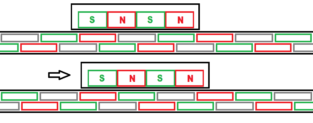
This is roughly to scale: the coils are 4mm wide with a staggered 2mm spacing, the magnets are 3mm wide, and each half-step is 1mm. Note how the magnets line up with the edges of the coils.
The three strings of coils run the full length of the track, so in theory only three wires are needed to drive everything. In practice, to keep the voltages reasonable, one 3-wire power feed is needed for every 1.0-1.5m of track. Each set of points or each stop section can require anything from two to six additional power feeds, as well as switching electronics, so the complexity increases rapidly for a more elaborate layout.
Each section of track has a 3-wire power feed at one end, and a termination point tying all three strings of coils together at the other end. Each power feed joiner piece terminates one section and starts another. For a small oval with just one power feed, the track wraps around so that the termination is right next to the power feed, and a single power feed joiner does both jobs.
The controller is similar to a conventional model rail PWM type, but with radically different software and 3 outputs to drive the 3 strings of coils instead of the usual 2 for 2 rails. It is used like a traditional model rail controller, with speed and direction controlled by a conventional centre-off knob (potentiometer).
