The next few posts will cover how I brought the different hardware subsystems to up and running, including working sample code.
This post covers a very basic RCC, GPIO, and SYSTICK inplementation, and uses them to... blink the LED. The same as the first part, just done my way! Very exciting.
This post covers a very basic RCC, GPIO, and SYSTICK inplementation, and uses them to... blink the LED. The same as the first part, just done my way! Very exciting.
Introduction
I have extracted a few register and bit definitions from some of the official libraries, but these have been stripped down to the bare essentials, only including the features I currently needed.
The files Makefile, stm32_ls.ld and stm32_startup.c are minimally modified versions of the blinky code from LEAP#549.
Everything else has basically started from scratch: stm32.c and stm32.h for the libraries, and main.c for the application. These snippets are actually cut-down versions of the model rail application. This code is still evolving, so more files, cleanups, error handling, etc. will be added in future.
Accessing Registers
Different STM libraries use different register access techniques. I have adopted one that suits me, with a struct for each peripheral and a global pointer to it, so accesses are of the form "DEVICE->REGISTER".
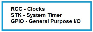
RCC / CLOCK
The sample code first sets up the system clock, using the HSE (High Speed External) mode to generate the maximum 72MHz from the 8MHz crystal on the board. The HSI (High Speed Internal) oscillator is left running, since a number of peripherals will require it.
The model railway application is not battery operated, so power consumption by the CPU is not a factor. If it was, a much lower clock frequency would be used and it would probably be best to remain on the HSI and not activate the HSE. However, EMF might become an issue, so the clock frequency might have to be reduced in future.
The RCC also provides the clocks to drive most of the internal peripherals, so the appropriate RCC bits (usually in the APB2ENR register) need to be set when initialising each peripheral. For now, that is just the GPIO module.
SYSTICK
The system timer is incredibly easy to set up, and is used here to generate an accurate 1ms tick that all system timing will be based on. Just set the counter value, then turn it and its interrupt on.
The basic delay function timerDelay() waits until N milliseconds after the last time it should have returned. This ensures that occasional long delays in the main loop will not throw out the timing. In the sample code, the loop runs every 20ms. Even if one iteration takes 30ms or so (this can't happen yet), everything drifts back into sync as soon as possible. Sometimes, however, a simple "wait for N ticks to pass" might be better.
Different STM libraries use different register access techniques. I have adopted one that suits me, with a struct for each peripheral and a global pointer to it, so accesses are of the form "DEVICE->REGISTER".
RCC / CLOCK
The sample code first sets up the system clock, using the HSE (High Speed External) mode to generate the maximum 72MHz from the 8MHz crystal on the board. The HSI (High Speed Internal) oscillator is left running, since a number of peripherals will require it.
The model railway application is not battery operated, so power consumption by the CPU is not a factor. If it was, a much lower clock frequency would be used and it would probably be best to remain on the HSI and not activate the HSE. However, EMF might become an issue, so the clock frequency might have to be reduced in future.
The RCC also provides the clocks to drive most of the internal peripherals, so the appropriate RCC bits (usually in the APB2ENR register) need to be set when initialising each peripheral. For now, that is just the GPIO module.
SYSTICK
The system timer is incredibly easy to set up, and is used here to generate an accurate 1ms tick that all system timing will be based on. Just set the counter value, then turn it and its interrupt on.
The basic delay function timerDelay() waits until N milliseconds after the last time it should have returned. This ensures that occasional long delays in the main loop will not throw out the timing. In the sample code, the loop runs every 20ms. Even if one iteration takes 30ms or so (this can't happen yet), everything drifts back into sync as soon as possible. Sometimes, however, a simple "wait for N ticks to pass" might be better.
GPIO
The GPIO functions are a simple wrapper to blend all three ports (A, B and C) into one unified interface. The functions are interrupt safe, so can be used in both normal code and interrupt routines, and they will not conflict. The writeMultiple function writes several bits simultaneously, as long as they are on the same port. It also clears any bits that need it before setting others. I use this feature to ensure that my push-pull FETs never turn on together, with a delay of 1-2us or so between them. The GPIO register used here does this anyway, but on a much shorter timescale, so I am just playing it safe.
The Sample Code
| blue-pill-bare-metal-blog2.zip |


 RSS Feed
