
This part expands on the bare bones program, adding basic ADC reads (although only the simplest of several modes), and simple interrupt-based serial comms through a USART. Only the TX side is implemented for now, since this is intended to be used only for debug output. It also does not use DMA buffering, although that would permit faster speeds.
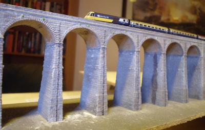
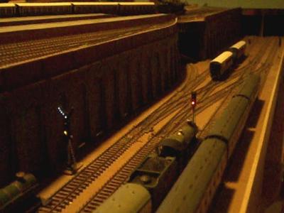
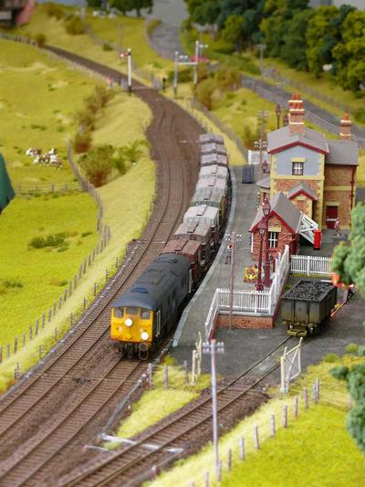
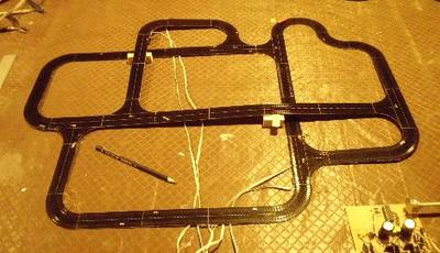
The software assumes that the serial port is on PA9 and PA10, the default pins for USART1, and is wired to a suitable USB-to-serial converter and then handled by a terminal emulator program such as PuTTY. The ADC input assumes that a potentiometer has been attached to PA0 (Analog channel 0), wired across 3V3 and 0V. I use this as the speed control for the trains, cars, canal boats, etc., and as a convenient input during testing (one reason I haven't yet bothered with the USART's RX side).
The software assumes that the serial port is on PA9 and PA10, the default pins for USART1, and is wired to a suitable USB-to-serial converter and then handled by a terminal emulator program such as PuTTY. The ADC input assumes that a potentiometer has been attached to PA0 (Analog channel 0), wired across 3V3 and 0V. I use this as the speed control for the trains, cars, canal boats, etc., and as a convenient input during testing (one reason I haven't yet bothered with the USART's RX side).
ADC
The processor's ADC subsystem can do all sorts of wonderful tricks, using DMA to read an arbitrary sequence of inputs into memory continuously so that the values can be easily read out at any time, any place. This code, however, just uses the most basic approach of only reading a single channel when needed. It's a start!
As usual, the appropriate RCC clock bit has to be set to enable the ADC subsystem, and the clock frequency has to be set to ensure an adequate conversion time. With the CPU clock set to its maximum of 72MHz, the ADC clock has to be slowed down to less than 14MHz, which still gives conversions fast enough for most applications.
The startup sequence is straight out of the manual, calibrating the device before it gets used. Performing a conversion involves building up a list of inputs to sample, which is just a single instance in this case, and then starting the process running. The results are returned as a 12-bit unsigned number, with 0 for 0.0V and 4095 for 3,.3V.
USART
My project uses USART1 as just a basic debug output, so handles basic text in TX mode only. It makes use of the USART1 interrupt, and I choose to limit the baud rate to 38400 which is one interrupt every 260us or so. Interrupts much more frequent than this are things I try to avoid, so you should use DMA to handle faster rates. 57600 would also be OK, but that is a reasonable upper limit for this technique.
This peripheral needs the AFIO unit to be active, even if you don't want to remap the port's I/O pins to their secondary values, so both the USART and AFIO clock enable bits have to be set in the RCC. Very conveniently, most of the USART registers default to values suitable for a basic serial port. Really all that needs to be done is set the baud rate and enable the TX and RX sides, and the USART itself.
There is a trick with the baud rate, however. The programming manual (and the standard libraries) do some complex calculations to determine the integer and fractional parts to be written to two parts of the BRR register. On this particular device, the register fields perfectly match the original value, so you can skip the whole process and just write the original number straight into the register! Feel free to check my logic, but you get the same value either way. Just the system clock divided by the baud rate: 72000000 / 38400 in the example.
Writing a serial handler can be tricky: the steady state interrupt case (second to last-but-one character) is simple, but starting and stopping can involve some awkward logic. This one, however, is not too bad. The hardware sets the TXE flag whenever the TX buffer is ready to accept more data, and this generates an interrupt. As soon as the data is written, this flag clears so that is very simple. After the last character is set, the interrupt code simply masks the interrupt, leaving the TXE flag set and waiting and suspending further interrupts. When the put function make the first character of a new transfer available, it simply unmasks the interrupt again. The interrupt routine immediately runs, grabs that first byte, and away everything goes. Quite elegant.
I have also added a basic printf() function, since I still find it the most comfortable way to generate formatted output of numbers, strings, etc. It isn't quite complete, but handles most of the common data types.
The Sample Code
In addition to its main job of blinking the LED, the program now reads the analog input once a second and outputs the result to the serial port. The same files as last time, just fleshed out a bit more.
In addition to its main job of blinking the LED, the program now reads the analog input once a second and outputs the result to the serial port. The same files as last time, just fleshed out a bit more.
| blue-pill-bare-metal-blog3.zip |


 RSS Feed
