Plymouth Citadel - Signals
After an early false start with the Dapol semaphores, I ended up using BR standard 4-aspect colour light signals. These are built from the kits by CR Signals, although as usual I have done a few things differently. This page mainly describes the signal construction and shows the results. For those interested, the electronic nitty gritty is covered in Electronic Tips - Colour Light Signals and Automation.
The layout has two signalling regions:
The layout has two signalling regions:
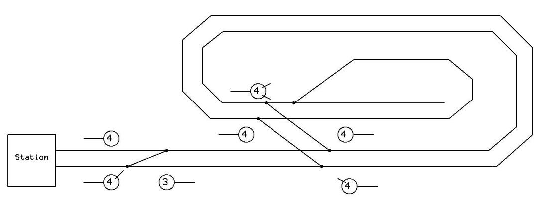
- the out-and-back main line which is handled by block working and some simple automation, so that up to 5 trains queue up before returning to the station. The signalling and trackwork here is designed to look like a busy 4-track main line with plenty of visible movement that doesn't require operator attention.
- the station itself, where the signals are controlled by a simulated interlocked manual lever frame.
First Stage - The Main Line
The first stage is the seven automatic signals on the main line (plus one spare), along with an updated version of the out-and-back automation. Each signal is controlled by its own computer (a PIC16F690 microcontroller), handling the signal itself, two optical sensors using LDRs (light dependent resistors), stop and slowdown relays configured for both loco-hauled and push-pull trains, interlocking with the points and a special timed mode for the continuous runs (in this mode, there is one signal on each oval, so they go red as a train passes then work up through the aspects so it looks like normal block working). The complete control circuitry for the seven signals fits on one circuit board the same size as the earlier relay-based automation board it replaces.
The first stage is the seven automatic signals on the main line (plus one spare), along with an updated version of the out-and-back automation. Each signal is controlled by its own computer (a PIC16F690 microcontroller), handling the signal itself, two optical sensors using LDRs (light dependent resistors), stop and slowdown relays configured for both loco-hauled and push-pull trains, interlocking with the points and a special timed mode for the continuous runs (in this mode, there is one signal on each oval, so they go red as a train passes then work up through the aspects so it looks like normal block working). The complete control circuitry for the seven signals fits on one circuit board the same size as the earlier relay-based automation board it replaces.
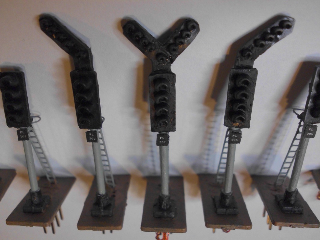
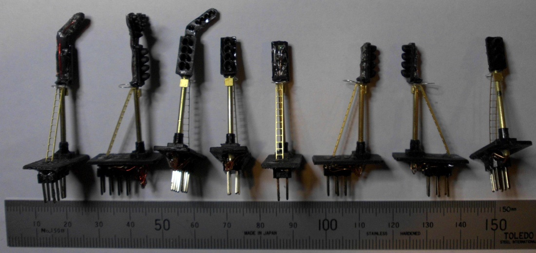

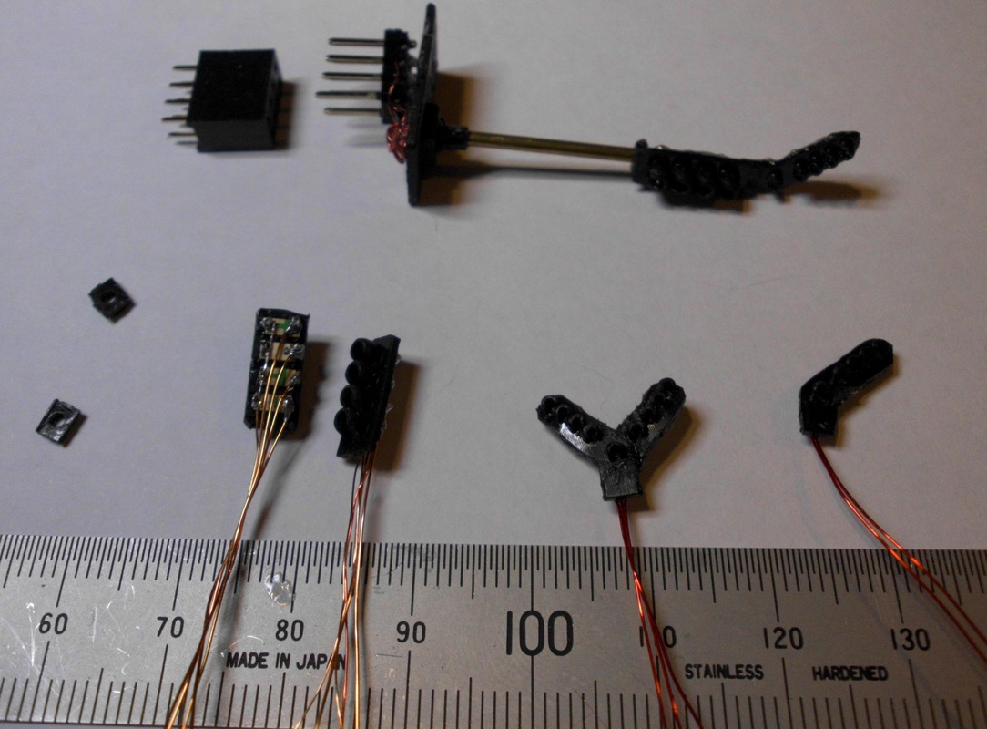

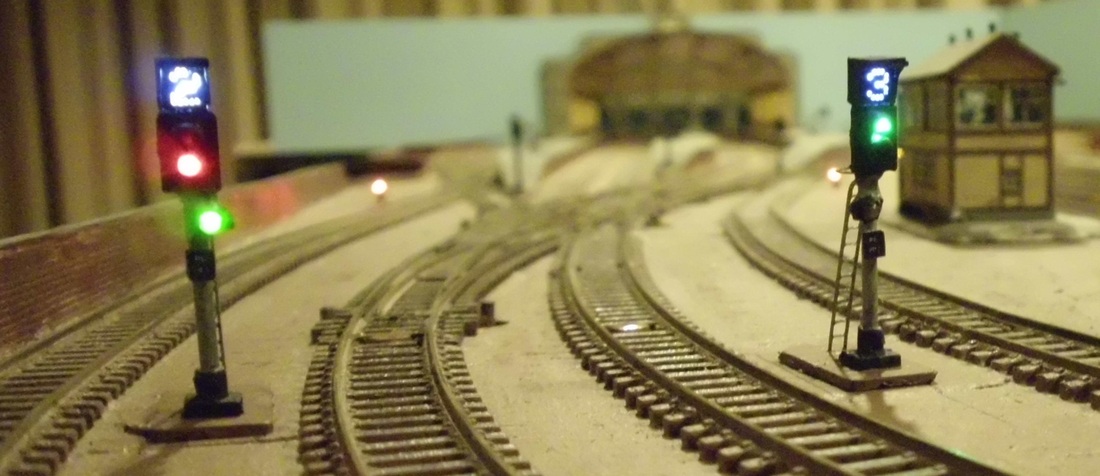
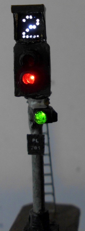
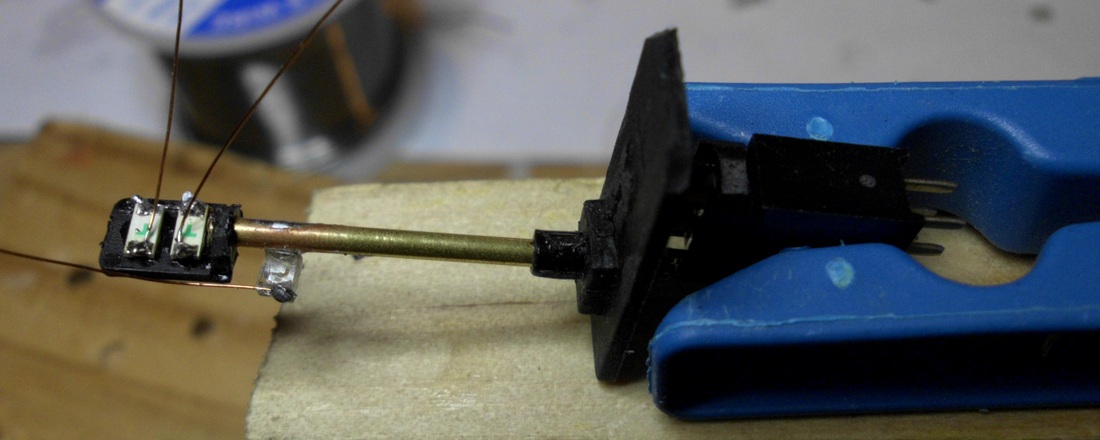
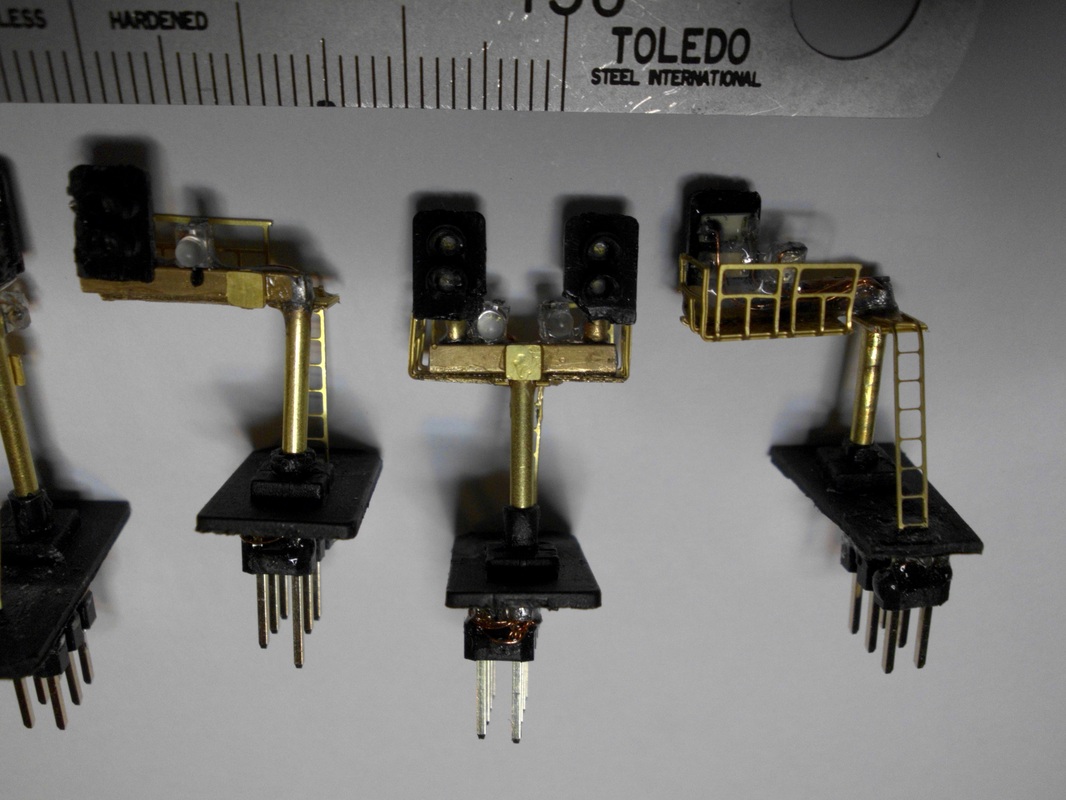
I liked the kits from CR Signals best out of the several brands I looked at, although as usual I ended up making some changes. The signal heads are somewhat over scale, especially the boxes that cover the back of the signal. The kits come with two options: the original type with larger LEDs and a plastic back cover, and an alternative set of smaller LEDs with a smaller brass cover. I found the former looked too large and clunky, while the latter was a bit too hard to assemble, so I compromised. I used the larger LEDs but omitted the back cover entirely. I then sealed the back using a couple of coats of PVA glue. This is more compact than using the supplied covers, but the resulting shape is somewhat irregular. When painted black, it is fine at any reasonable viewing distance. The signal head baseplate had to be cut down drastically to match, and I replaced the supplied safety ring with one made of wire.
Paul at CR Signals was kind enough to supply me with some feather mouldings, so I was able to attempt to build my own junction feathers. This was fiddly in the extreme, resulting in a couple of blobs of melted plastic and LEDs, so I see why this is not normally offered as a kit. In the end they worked out OK, as long you don't look too closely. I chose to wire the feather LEDs in series to get consistent brightness, though this requires a 20V+ supply (which I already had for the point motors). I chose to alternate the LED orientation in order to simplify the head wiring, but with hindsight would have obtained a more even LED brightness if they were oriented the same way round.
The signals are built on dual-in-line headers so they just plug into sockets under the baseboard. The signals can be removed for maintenance or for safety when the rest of the heavy scenic work gets done.
Second Stage - The Station
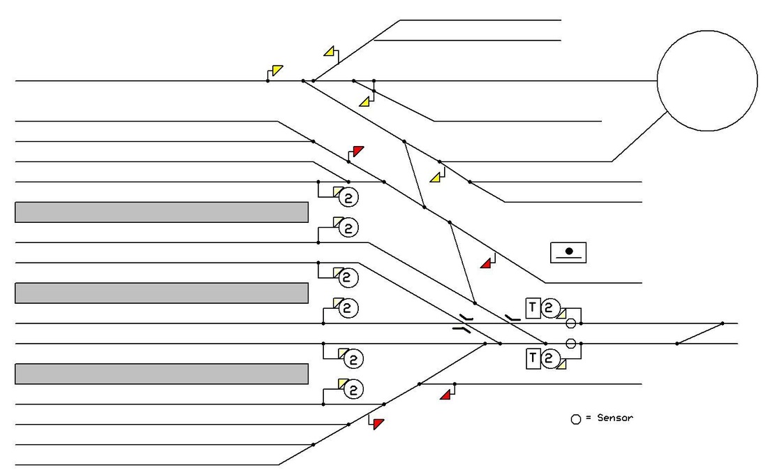
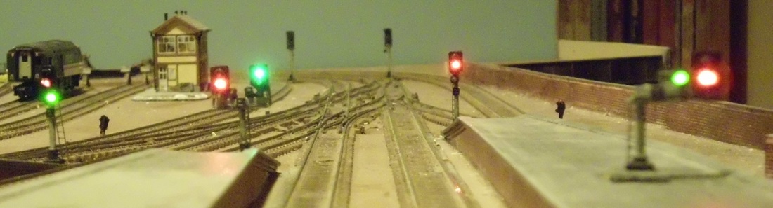
The station has eight 2-aspect signals, all with auxiliary calling-on or shunt heads plus theatre indicators on two, plus eight standalone ground signals. The signals and theatre indicators are modified CR Signals kits, with the subsidiary heads each made from a single green gull-wing SMD LED. The ground signals are home-made with two of the same type of SMD LEDs soldered onto a piece of brass tube. I did attempt to make modern British position-light ground signals (the triangular white/white/red type) using faceplates from N Brass Locos dummy signal kits, but found it too difficult to get consistent results.
All train movements within the station are controlled by the signals, with arrivals and departures controlled by the running signals and shunt moves within the station by the ground and subsidiary signals. Each signal can control multiple possible movements and routes. The signalling plan is simplified from what a station of this size would actually have, with only 21 levers instead of the 40-50 that would normally be required. To do it properly, most signals should have multiple heads or theatre indicators.
The signals are controlled from a bank of 21 toggle switches set up as a simulated interlocked lever frame, with each switch controlling one signal head. All except one of the MPD ground signals are permanently left at danger (yellow) or switched automatically by the points in the MPD. If a lever (!) is pulled when the interlocking says it should not, its signal will stay at danger. There is a a full set of panel repeaters that show the actual state of each signal. These provide the necessary operator feedback for interlocking - pulling a switch should set that signal to green or yellow, so if nothing happens on the panel the operator knows to put the switch back and see what was missed.
The signals are fully interlocked with the points and any conflicting signals, except that there is no attempt to restrict the changing of points. Changing any point will reset all associated signals to danger. There are also two LDR sensors in the station approach that also reset signals to danger as trains pass on the main lines.