Electronics - Using LEDs
This is a reprint of an article submitted to "The Clearing House", the journal of the British Railway Modellers of Australia, as a follow-on to an article by another author. There are a few references here to that article, but this pretty much stands alone.
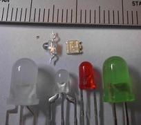
A selection of useful LEDs for modelling. Surface mount LEDs at the top, tri-colour LEDs bottom left, and conventional 3mm and 5mm LEDs bottom right.
Selecting Resistors
In practice, you can generally assume that a red, green or yellow LED drops 2V, and a blue or white LED around 3.5V. Most 12V DC power supplies actually put out around 12.5-13.0V when lightly loaded, so you should generally play safe and round up to the next higher resistor value to compensate. When using 12V, 560 ohms would be a good choice for 20mA, and 470 ohms for 25mA.
Since running an LED at 20mA at just over 12V works out very close to the 1/4 watt rating of a low power carbon resistor, it is generally better to maintain some margin and use a 1/2 watt resistor. These are the same physical size, only cost about 1 cent more, and have better heat tolerance.
Since running an LED at 20mA at just over 12V works out very close to the 1/4 watt rating of a low power carbon resistor, it is generally better to maintain some margin and use a 1/2 watt resistor. These are the same physical size, only cost about 1 cent more, and have better heat tolerance.
Brightness and Colour
Different types of LEDs can vary by x100 or more in intrinsic brightness, so you need to choose a combination of LED and current that is suitable for your application. Loco headlights, colour light signals and some control panel applications may require full brightness, but other uses such as tail lamps, street lights and building illumination will often look better at dimmer settings.
If you use a bright high-efficiency LED, you can get the same amount of light with a lower current.
Before using an LED in a new application, try out various resistors to see which gives the most suitable level of illumination. Doubling the resistor size and halving the current for each attempt should give good enough results (560 ohm=20mA, 1K=10mA, 2.2K=5mA, etc).
LEDs tend to be commodity parts, often bought in anonymous bulk, so you may have trouble obtaining identical devices in the future. This can be a problem if you need matched LEDs for control panel route indicators or colour light signals (especially searchlight types). It pays to buy a reasonable number of spares at the beginning. Electronics shops also tend to give significant discounts for larger quantities of 10+ or 25+.
Several different variants of each colour are available. Some shades of green are actually almost yellow, and some oranges are almost red. These can also look different in unusual lighting conditions (e.g. nighttime operation).
Most LEDs are encapsulated in plastic of the appropriate colour, but you can also obtain water clear LEDs (clear plastic) or clear diffused (milky white). Each is better for certain modelling applications.
Viewing Angle
Most LEDs have a fairly narrow viewing angle, being brightest when viewed end-on. This is fine for headlights, signals and most control panel applications, but not so good for anything viewed from the side (illuminated buildings, anti-collision lights, etc.).
I have found that the best LEDs for side-viewing are the special two-legged bi-colour LEDs available from most electronics stores. They come in red/green and yellow/green types, but you only need to use one colour. Caveat: the current Jaycar catalogue has the specs for two of their 3mm types swapped, so you might want to ask them to demonstrate before buying!
I have found that the best LEDs for side-viewing are the special two-legged bi-colour LEDs available from most electronics stores. They come in red/green and yellow/green types, but you only need to use one colour. Caveat: the current Jaycar catalogue has the specs for two of their 3mm types swapped, so you might want to ask them to demonstrate before buying!
Power and Heat
LEDs are reasonably efficient low power devices (especially when compared to incandescent lamps), but their current limiting resistors are anything but. Running LEDs on 12V means that 5/6ths of the total power is directly wasted as heat in the resistors, with the remaining 1/6th being used for light (and still more heat) in the LEDs.
If a resistor is dissipating 1/4 watt for a typical 20mA LED, it will be hot to the touch. If you have 100 such LEDs under a control panel, you will be generating 25W of heat under the panel (equivalent to a small mains-powered desk lamp).
When using LEDs at higher currents/brightness, try to keep a small air gap around each resistor. A couple of millimeters should be enough, especially if the surface is not horizontal and so provides some airflow (e.g. a sloping control panel). Be careful if a resistor has to touch plastic parts or be embedded in glue when making an illuminated model. This is yet another reason to use lower currents (with brighter high-efficiency LEDs). For these cases, I suggest trying out the LED/resistor combination on the bench first. Let it run for 5 minutes, then finger-test the resistor. If necessary, you can use two resistors of half the value in series (e.g. 2x270 instead of 1x560). This halves the heat dissipated by each resistor.
LEDs in Parallel
Another reason to avoid running two LEDs in parallel off one resistor is that while the resistor sets the total current/brightness of the pair, it is then up to the LEDs to share this out between themselves. Tiny variations between the LEDs can cause major differences in their respective brightness. They may even start out the same, but drift apart as they age.
One parallel case that does work well is when only one LED of the pair is switched on at a time. Examples include the red and green aspects of a signal or the two route settings of a turnout on a control panel.
One parallel case that does work well is when only one LED of the pair is switched on at a time. Examples include the red and green aspects of a signal or the two route settings of a turnout on a control panel.
LEDs in Series
If you need multiple LEDs on the same circuit, you can share a resistor and wire the LEDs in series. This changes the resistor calculation a little. For example, with two LEDs off 12V you get (12-2-2)=8V across the resistor instead of (12-2)=10V, so for 20mA you would need 400 ohms instead of 500 (say 470 instead of 560 using real values).
This is also far more efficient in terms of power and heat: two LEDs in series means half the total power consumption. Fifty LEDs at 20mA wired this way require 0.5A instead of 1.0A. Wiring three LEDs in each chain would reduce the power (and heat) by a factor of three.
You do not get something for nothing here - each LED still requires and gets the same amount of power, but we are simply making better use of those wasteful resistors.
There is one slight drawback to the series approach - with a lower voltage across the resistor, minor variations in the transformer output voltage have a proportionally greater effect on the total brightness. To control this, I suggest limiting the LED chain to no more than half the supply voltage (e.g. for 12V, 3 normal LEDs or (just maybe) 2 blue/white LEDs).
Unusual Voltages
Most railway modellers will run their LEDs off 12V DC, but any of the common model railway voltages are fine - just remember to use the correct voltage in the resistor calculation and be wary of higher power/heat dissipation for voltages above 12V. You may need to reduce the current/brightness and/or use higher efficiency LEDs for these cases.
You can run LEDs on 15V AC (they are just diodes after all), but since they will only be powered for half a mains cycle the brightness will be half what you expect and you might detect a faint flicker or pulsation. If you use a lot of LEDs this way, try to wire half of them one way round and the other half the other way to balance out the load on each phase. A good trick when illuminating buildings with AC is to wire two LEDs in parallel with a single resistor (yes, I know) but with one LED reversed head-to-tail.
*** Update - it was pointed out to me that LEDs have a limited tolerance for reverse voltage, and running single LEDs off 15V AC will probably destroy the LED. My practical experience was with lower voltages, so I missed this. It is OK to use them back-to-back, but you will get flicker.
The highest model railway voltage I have encountered being used for LEDs was 48V DC (for running Telecom/PMG relays). This does work, but the high power consumption and heat dissipation from the resistors is excessive and not really recommended.
