Electronics - Fleischmann Turntable Control by Rotary Switch
This article describes how to directly control a Fleischmann turntable with a rotary switch: when you move the switch to position 10 the table turns to track 10. Simple - set and forget. Fleischmann actually sells an accessory controller that does this job, but it costs about as much as the turntable itself!
The Conventional Approach
The Fleischmann turntable is generally considered to be the high-end ready-to-run model railway turntable. It is fully indexed and supports up to 48 tracks. It is not, however, cheap. The unit comes with a large custom control switch designed to fit in with Fleischmann's diagrammatic control panel products.
Some modellers use their own controls rather than the supplied switch. This requires two normal toggle switches. A double pole switch controls the turntable rotation direction and which end of the bridge is live, and a single throw on/off switch starts and stops movement. The direction switch is wired as a standard reversing switch, with 12V DC in and the turntable's red and yellow wires out. The other switch is wired to connect the turntable's grey and yellow wires together to activate the table.
What all of the above methods have in common is that they are still manual - the operator must start the table moving, watch and wait until the bridge is almost at the right track, then stop the table at the right track.
Fleischmann has clearly designed the turntable to minimise the amount of wiring required. Two wires feed track power to the bridge via a pair of slip rings. The bridge then feeds power to the selected track through two sliding contacts under the ends of the bridge rails. Since the bridge may be aligned with two tracks directly opposite one another, only one end of the turntable bridge is live - this is controlled by the turntable direction switch. You generally need an additional reversing switch to control the track feed polarity to the turntable, and you have to get both of these direction switches right in order to move a locomotive onto or off of the table.
There is also a track polarity issue with the turntable. The slip rings that feed power to the bridge do not have gaps half way around the table, so you must manually match up the track polarity with the end of the bridge every time you use the table or cause a short circuit. Some modellers (including myself) rewire the turntable to receive bridge power from the selected track rather than the other way round to avoid this hassle.
I have used a number of these turntables on other people's layouts, and find this to be a fairly clumsy procedure. There are also sometimes reliability problems with the under-rail contacts - you occasionally have to give the bridge a slight nudge to ensure that power reaches the track.
Simple DCC implementations do much the same thing through different means. More sophisticated decoders designed specifically for turntable applications can achieve the same go-directly-to-track result. Many use a reversing-loop decoder to handle the polarity issue.
The Rotary Switch Approach
I do things completely backwards from the way Fleischmann intended. A 2-pole rotary switch connects track power to exactly one of the roads around the turntable. When the bridge is aligned with that road, the bridge is powered from the selected track through the sliding contacts under the rails. The two now-unused yellow wires from the turntable bridge slip rings are now available for other purposes.
The manual on/off switch is replaced by a simple relay timer circuit. Once activated, this drives the turntable for just over a minute and then cuts off - enough time for a complete 360 degree rotation and an operator change of mind. This timer (and hence the turntable) is started whenever the rotary switch is moved. When moving, the bridge sweeps past all the disconnected tracks until finally reaching the one selected by the rotary switch. The ground rail of this track touches one of the moving bridge rails and so completes a circuit that cuts off the timer. The turntable then completes its movement normally and stops at this track.
The whole control system consists of a 2-pole rotary switch and the timer circuit, plus a couple of other odds and ends. The timer start and stop inputs have some special protection circuitry since they connect directly to the track. Otherwise, if a locomotive happens to be parked across a rail join then unexpected positive or negative traction voltages could feed into the circuit and cause problems. There are also a number of diodes connected to the rotary switch to detect switch movement and start the timer.
The tracks around the turntable need to be wired a certain way, and a lot more wiring is required than when using the conventional approach. There are also a number of other assumptions about how everything must be configured.
Assumptions & Comments
- The control circuit needs a 12V DC supply that shares its ground with the track and stays at +12V relative to that ground. If using conventional cab control, this means that you cannot share the same transformer winding used by any of your controllers. You will probably need a separate dedicated accessories transformer, but that is a good policy anyway.
- You still need a direction switch to control the rotation direction. If you are sneaky enough, you can set up the table so that all normal operations are in a single direction and the switch will rarely be used.
- I have assumed that there are no turntable tracks directly opposite one another. The bridge would move to these roads correctly, but it would then join the two roads together electrically - both roads would be powered simultaneously. If necessary, it should be possible to get around this restriction using additional relays and changes to the track wiring, but I have not attempted it. See below for a suggested approach.
- I feed power to the bridge from both ends: the dummy tracks opposite each road have duplicate feed wires soldered to them. I also have shorted out the rail gaps on the bridge itself to nullify the turntable's directional track feed feature. This ensures that the bridge is always fed through two sets of contacts, eliminating the traditional nudge-the-bridge reliability problem. You will need to do one or both of these things to make the system work correctly.
- If a locomotive is parked across a rail join leading to a turntable track, this can cause the control circuit to mistake this road for the destination road and stop the table prematurely. I have wired my entry and exit tracks so that they are powered by the normal layout feeds: only the little connector sections are wired to the turntable. On the other hand, all of the storage roads are fully wired to the turntable.
- The rotary switch has to be a 2-pole unit and switch both rails of each track. This may require some rewiring if you use a common return system. It is essential that all other tracks be completely disconnected for the stop detection system to work.
- It is easy enough to find 2 pole rotary switches with up to 6 positions, and if you look around a bit you can find 12 position versions (I got mine from Altronics down here in Australia). If you have fewer tracks than switch positions, I recommend wiring the extra positions as duplicates of your main entry or exit tracks. If you leave them unconnected and select them by accident, the turntable will just keep turning until the timer expires. If you need more than 12 tracks, you will have to use multiple switches. For 24 roads, you could use 2 rotary switches and a toggle switch to choose between them. I chose to use a 12-road configuration for my turntable because of the available rotary switch. I have track components and space for a 13th road, but the operational simplicity of a single switch won out.
- You will need to carefully choose the polarity of each track when you wire it up. This is an arbitrary decision that does not affect the control system, but may affect how you run the layout. When wiring the dummy tracks opposite each road, be sure to get the polarity the same.
Circuit Description
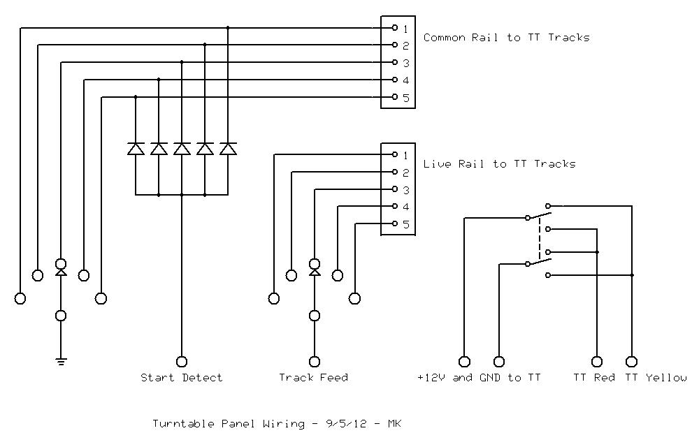
The panel wiring is straightforward: the rotary switch(es) distribute one pair of track feeds to all of the turntable roads, and the direction switch is wired as a simple reversing switch. I use a 34-wire IDC cable to connect to the panel: 26 to the rotary switch, 4 to the reversing switch and 4 spare.
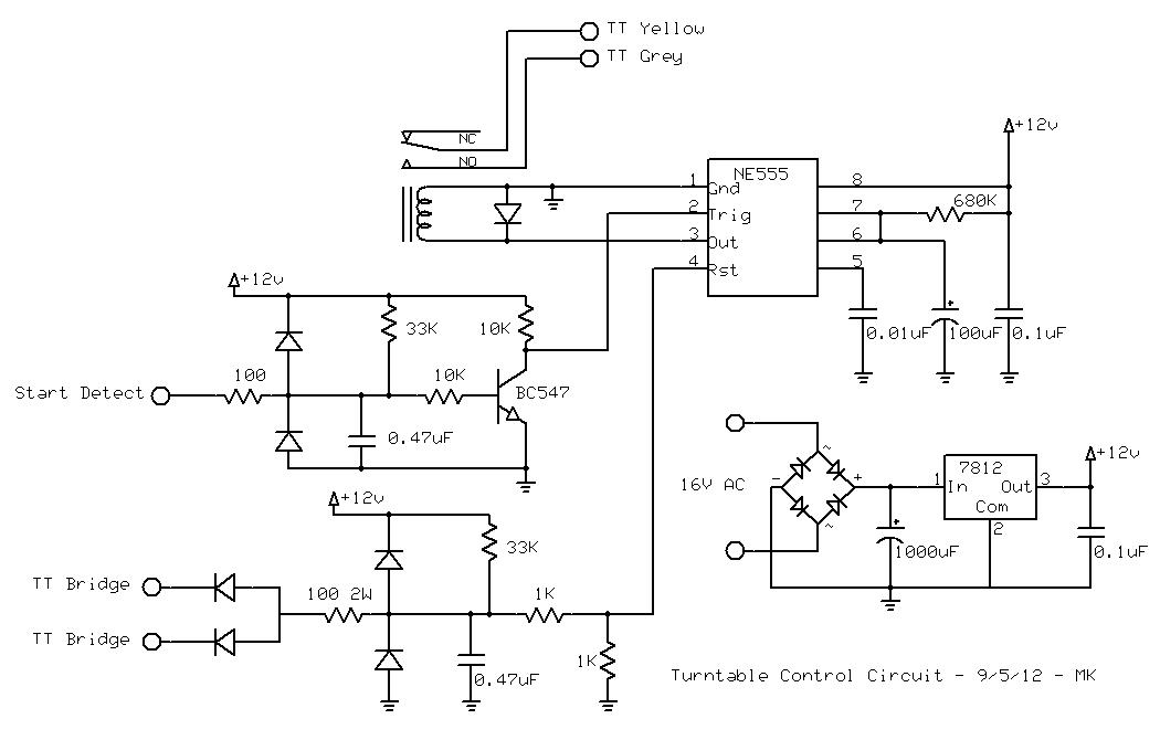
The IC/relay power supply is a conventional 12V regulated supply. The maximum current draw is less than 100mA, so no heatsink is required for the regulator.
The heart of the circuit is an NE555 timer chip configured as a standard monostable. This generates an 80 second output pulse when it gets a low voltage on its input. A low voltage on its reset line stops the timer. The timer drives a relay directly, so make sure you use the bipolar version of the chip, not CMOS.
The start and stop inputs have some serious voltage protection circuitry, with clamping diodes, current limiting resistors and glitch-suppression capacitors. This protects the 555 from +12V/-12V or higher traction voltages if someone parks a locomotive across a rail join. The input circuit also has an inverter, since the start signal from the rotary switch is the wrong polarity.
The timer start circuit is connected to a network of diodes connected to the ground pole of the rotary switch. When the switch is in any valid position, the ground is connected to one of the tracks and that track's diode pulls the start input low. When the rotary switch is moved, the break-before-make contacts ensure that just for a moment the ground connection is lost. A pullup resistor pulls the start input high and triggers the timer. Any additional switch movements or contact bounce are ignored.
The timer stop circuit is connected to the turntable bridge rails through 2 diodes. A high-value pullup resistor puts +12V on both rails, but with so little current behind it that locomotives will never notice it. This is similar to the way track circuit detectors work. When the moving rail touches the ground rail of the destination track, a reset pulse is sent to stop the timer. This rail contact is more reliable when in motion than when stationary, so should always detect the stop track, even if you choose not to wire up the dummy tracks opposite the destination..
The timer reacts much more quickly than the turntable control relays, so if you get start and stop events in rapid succession then the turntable does not move. This can happen when the layout power is first turned on.
The panel wiring is straightforward: the rotary switch(es) distribute one pair of track feeds to all of the turntable roads, and the direction switch is wired as a simple reversing switch. I use a 34-wire IDC cable to connect to the panel: 26 to the rotary switch, 4 to the reversing switch and 4 spare.
The IC/relay power supply is a conventional 12V regulated supply. The maximum current draw is less than 100mA, so no heatsink is required for the regulator.
The heart of the circuit is an NE555 timer chip configured as a standard monostable. This generates an 80 second output pulse when it gets a low voltage on its input. A low voltage on its reset line stops the timer. The timer drives a relay directly, so make sure you use the bipolar version of the chip, not CMOS.
The start and stop inputs have some serious voltage protection circuitry, with clamping diodes, current limiting resistors and glitch-suppression capacitors. This protects the 555 from +12V/-12V or higher traction voltages if someone parks a locomotive across a rail join. The input circuit also has an inverter, since the start signal from the rotary switch is the wrong polarity.
The timer start circuit is connected to a network of diodes connected to the ground pole of the rotary switch. When the switch is in any valid position, the ground is connected to one of the tracks and that track's diode pulls the start input low. When the rotary switch is moved, the break-before-make contacts ensure that just for a moment the ground connection is lost. A pullup resistor pulls the start input high and triggers the timer. Any additional switch movements or contact bounce are ignored.
The timer stop circuit is connected to the turntable bridge rails through 2 diodes. A high-value pullup resistor puts +12V on both rails, but with so little current behind it that locomotives will never notice it. This is similar to the way track circuit detectors work. When the moving rail touches the ground rail of the destination track, a reset pulse is sent to stop the timer. This rail contact is more reliable when in motion than when stationary, so should always detect the stop track, even if you choose not to wire up the dummy tracks opposite the destination..
The timer reacts much more quickly than the turntable control relays, so if you get start and stop events in rapid succession then the turntable does not move. This can happen when the layout power is first turned on.
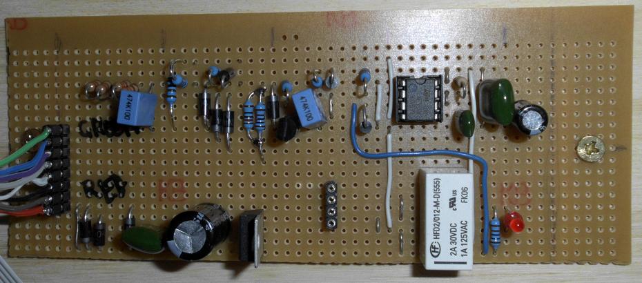
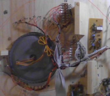
The control circuit - I was expecting development problems, so I left a lot more space than usual. It consists of a 555 timer and relay (right), some voltage protection circuitry for the start/stop inputs (upper left) and a power supply (lower left). The 4-pin connector goes to the direction switch.
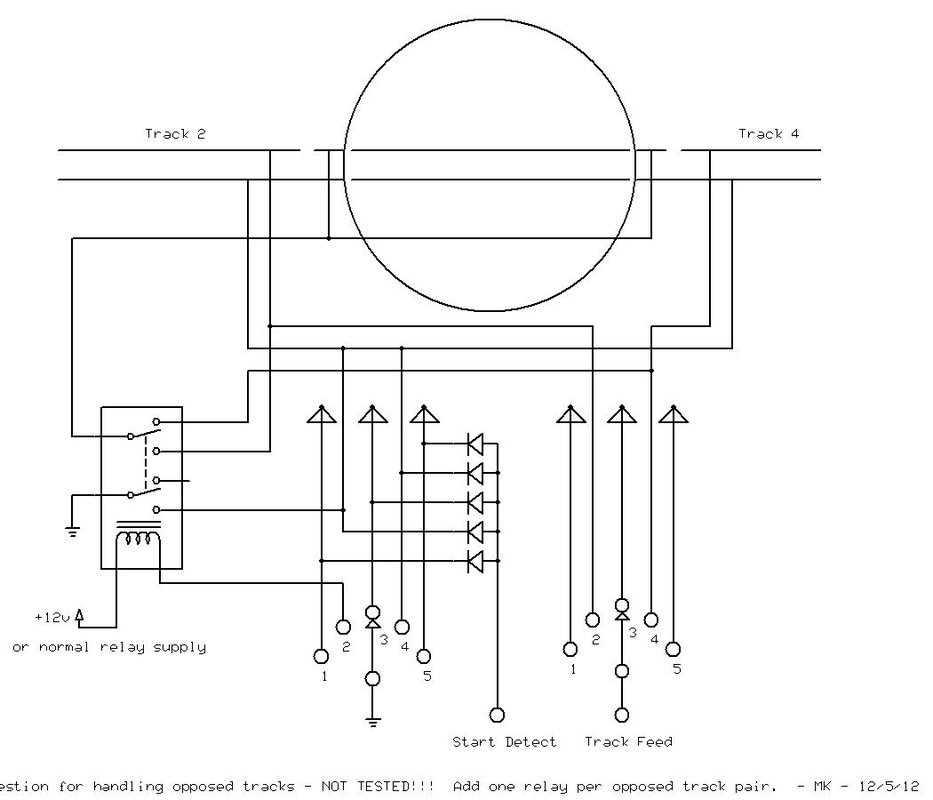
Handling Opposed Tracks - NOT TESTED!
It should be relatively simple to add support for a few pairs of directly opposed roads. Again, I haven't tried this but it seems simple enough to work. Each opposed pair needs a DPDT relay and gaps in each of the two live rails. This will probably require soldering feeds directly to the turntable extender pieces.
The ground pole of the rotary switch is used to activate the DPDT relay when one specific road of the two opposed roads is selected (track 2 in the schematic). This relay can be powered by the turntable circuit's 12V or by any existing relay supply, as long as this shares the same ground. Only one of these relays would be active at any time, so additional power consumption is minimal. One pole of the relay is used to simply replicate the normal ground-wire handling for this road. The other pole is used to choose one of the two roads' live rails to connect to the turntable stubs.