Electronics - Controller Types
There is surprisingly little on the web comparing the different varieties of DC controller for model railways, so this article attempts to summarize the four basic types and their characteristics. There is no single best way to power a loco - every method has its advantages and disadvantages, and its own group of ardent supporters.
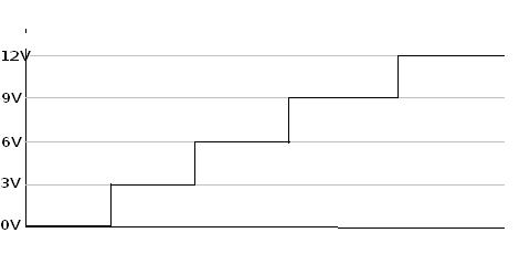
The basic concept is well known by everyone - controllers manage the train speed by varying the output voltage between 0V and (typically) 12V or so. Where they differ is in how they go about doing this, and what the consequences are for low speed control, starting, noise, motor heating, controller heating, complexity, cost, etc.
The key point is that the output voltage is an average voltage. If a controller is putting out 9V (75% power), this could be a steady 9V but usually it will be a series of pulses, with a maximum voltage significantly higher than this. Differences between controllers basically come down to the nature of these pulses.
Constant Voltage Controllers
The first type of controller puts out a completely steady voltage. For example, 75% power or 9V really means 9V. Some battery-powered controllers for very cheap train sets work this way, and some people use and recommend more sophisticated designs built around a voltage regulator circuit. Overall, they are rarely used for RTR locos.
The main advantage of this type is that the motor runs very smoothly, quietly and with minimal heating. On the other hand, low speed performance and starting characteristics are poor - the controller needs to be turned up to a fairly high setting to overcome static friction and start the train, then dialed back to something lower. Any minor problem at low speed can cause a stall.
This approach is only really suited to driving high-quality mechanisms, and is actually the recommended approach for particularly light weight coreless motors such as Portescap. It does not work at all well with typical model mechanisms, particularly the older types.
Controllers of this type also tend to generate a fair bit of heat within their circuitry, since they control the motor voltage by converting the unwanted part into heat - if running at half power, the loco gets 6V while the controller wastes the other 6V.
Summary: poor low speed, very good quiet running, cool locos, warm controllers, great for coreless motors.
Conventional or Dissipative Controllers
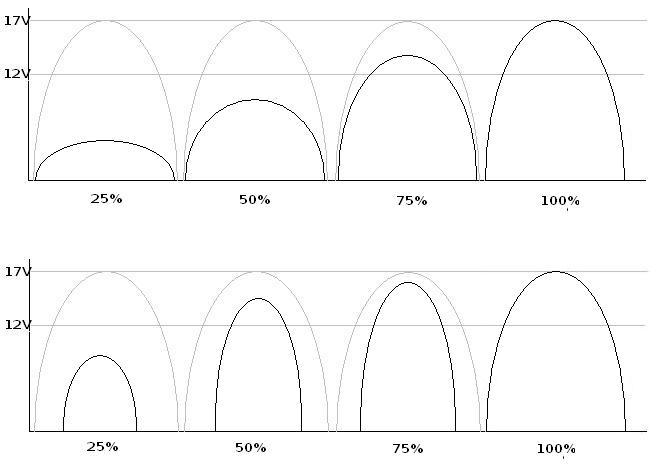
This is by far the commonest type of DC controller, especially with older products. It takes the pulsing 12V DC output of a transformer and rectifier combination and passes a variable fraction of this to the loco. The unused portion is converted to heat in the controller, so this type also tends to run hot.
The full-wave 12V DC from a transformer and rectifier is a form of pulsed power. Each cycle of the AC mains generates two sinusoidal pulses of 12V DC, so we get 100 or 120 pulses per second, depending on the country. Each pulse varies from 0V up to about 17V (40% above the average of 12V) then back down to 0V again.
This type of pulsed power is better at overcoming friction and unsticking sticky mechanisms than constant voltage. For example, if running slowly at 25% power with a 3V average, each pulse will peak at about 4V. The voltage changes smoothly, so the motors run nearly as quietly as constant voltage.
The simplest and cheapest form of this type of controller uses a variable resistance. This type offers very poor speed regulation, since it suffers from positive or adverse feedback (the opposite of modern feedback controllers). When a train climbs a hill, the loco slows and the motor asks for more power, so the resistance controller gives it less. When going down a hill, the loco asks for less power so the resistance controller gives it more.
More sophisticated products use either a variable transformer or a simple transistor circuit (old controllers that proudly describe themselves as "transistorised" fall into this class). These maintain a fairly steady average output voltage and so behave much better than the resistance type.
Some early controllers (for example Hammant & Morgan) offered a "pulse power" switch. This simply turned off half the rectifier and so skipped every second power pulse. You then had to dial up a higher setting to get the same speed, ending up with fewer but larger pulses. This worked quite well with older and heavier motors, but is not so good with smaller more modern types.
An interesting variant of this type puts a capacitor across the main output transistor, which effectively squeezes each output pulse, making them narrower and higher, but still well rounded and easy on the motor. This type can give very good and very quiet low speed running, but the capacitor needs to be fairly well matched to the loco. I used this type on my old layout Dunharrow, but a 470uF capacitor that worked superbly with my older Farish locos (a Castle taking 20 seconds to silently creep its own length) caused my newer Dapol locos to run amok (my 14xx had only two speeds: stopped and way-too-fast). I eventually fixed the problem by putting a three-position switch on each controller that switched in different capacitors!
Summary: fair low speed, quiet running, cool locos, warm controllers, the type that all others are compared to.
1) Conventional or Dissipative Controller.
2) Squeezed-Pulse Variant.
Chopped Full-Wave Controllers
The third basic type of controller also uses 12V DC full-wave power, but controls the speed by chopping out different parts of the full-voltage waveform. These generate taller and sharper pulses and so have better low-speed performance than the dissipative type, but this also creates more motor noise and heating. On the other hand, the controller itself runs cool.
The commonest type chops off the first part of each pulse. These were often known as SCR or thyristor controllers, and often used in hand-held designs. A rare variant of this chops off the last part of each pulse instead of the first, but these behave identically.
Another variant chops out the middle of each pulse, leaving twice as many smaller triangular pulses (200 or 240Hz). This is particularly suitable for small motors, such as N gauge.
Yet another variant chops off both ends of each pulse, leaving a very tall narrow pulse in the middle. This is very similar to the PWM type in the next section, with excellent low speed control but very noisy and hard on the motors. The comparatively slow pulse rate of 100/120Hz means that they generally perform worse than a true PWM design, which would usually be set up for 200Hz or more.
One minor drawback of all designs of this type is that the speed control knob feels less sensitive. A traditional dissipative controller has a linear response curve: the 25% setting on the knob gives 25% of full power (though not 25% of full speed), etc. With a chopped controller, most of the response is in a fairly narrow band near the middle of the range. There are some subtle design tricks that can be used to ameliorate this problem, and generally the improved running makes it a fair trade.
Summary: good low speed, noisy running, warm locos, cool controllers.
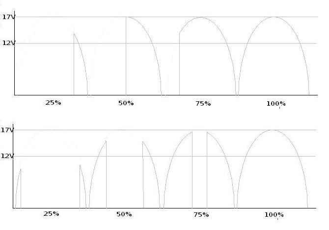
1) Basic SCR Controller.
2) Dual-pulse N Gauge Controller.
Square Wave Pulse Width Modulation (PWM) Controllers
The last basic type generates its own pulses at whatever rate the designer considers best (usually 200-300Hz). The peak voltage from the 12V input is stored in a capacitor, so the typical pulse voltage is about 17V. Speed control is done by varying the width of each full-voltage pulse. These narrow but tall and sharp pulses give the best low speed control and starting, but they are quite harsh on the locos and tend to be very noisy (locos really growl or sing) and can cause a lot of motor heating at sustained low speeds.
These controller designs can potentially supply more than 12V to the track, so the 100% power setting is generally set up to have less than the maximum possible pulse width, often the equivalent of about 13V or so.
This is generally the type found when the controller is described as a "pulsed" controller, although strictly speaking nearly all controllers are "pulsed".
Several variant or hybrid forms exist, all of which attempt to retain the superb low speed characteristics while minimising the drawbacks.
One approach is to greatly increase the pulse frequency, often to above the audible range: 20000Hz or more (sometimes known as "silent pulse power"). The side effect here is that each pulse now contains so little energy that most of the low-speed benefits are lost. The motor simply cannot react or even notice voltage changes at this rate, so it all behaves very much like a cool-running constant-voltage controller. This variant should actually be suitable for coreless motors (though I haven't tried this).
Another approach is to reduce the pulse voltage at lower speeds or when the loco is already moving. For example, on the Pentroller the speed knob directly controls the pulse width, while the feedback circuit adjusts the pulse voltage.
Yet another approach is to try to round out the pulses a bit, usually reducing the voltage as well at the lowest speeds . My own PWM design does this, effectively making each pulse into a shark-fin shape. A couple of computer-based designs I am aware of do something like this too, ramping the voltage up and down on each side, giving a triangular or sawtooth pulse.
Yet another approach varies the pulse width the usual way, but keeps the gap between pulses the same (standard PWM trades one off against the other). Another design always uses the same narrow starting pulse and does not widen it, but instead raises the base voltage between pulses as the train speeds up.
Summary: best low speed, noisiest running, warmest locos, cool controllers.
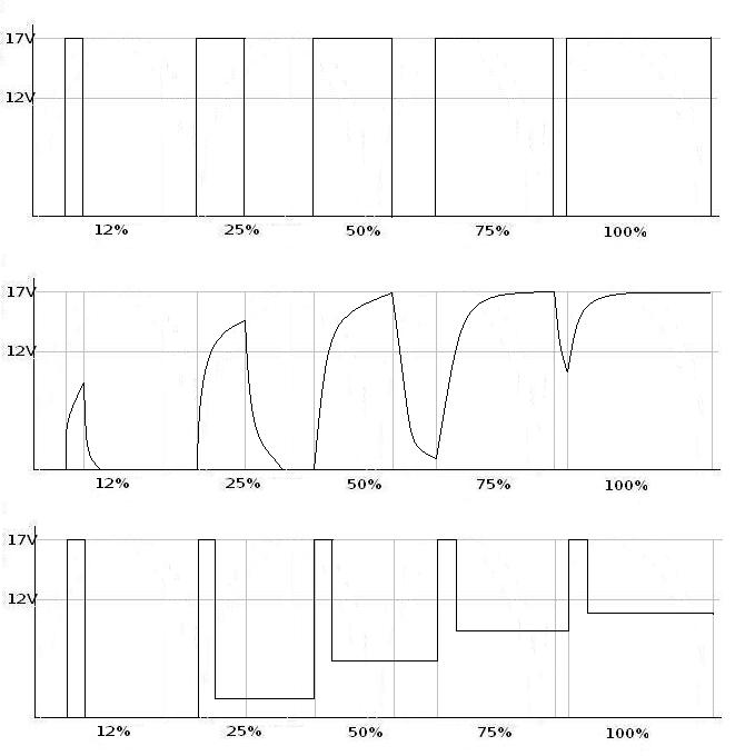
1) Basic PWM Controller
2) PWM with Rounded Pulses.
3) Fixed Pulse with Constant Voltage.
Feedback Controllers
These are not actually a different controller type, but more of an accessory to one of the above designs (usually PWM). I have a few thoughts on these on my Feedback Controllers page.
DCC
This article is really about conventional DC controllers, but a few words on DCC might be in order. As far as I know, all DCC decoders use a variant of PWM. This is a matter of practical necessity - for obvious reasons, the decoder cannot afford to generate a lot of heat and melt the plastic loco body. It is simply fortuitous that this approach turns out to be very good for low speed running. Decoders have a lot of advantages over a standard external DC controller, since they are always being fed with full power, are directly wired to the motor, and can be uniquely customised for that motor. There used to be a few high-end conventional controllers on the market with comparable features like loco selection and speed tables, but these have largely disappeared since DCC became popular. The vast majority of modellers seem to choose either low-end-DC, build-your-own-DC, or DCC.
Commercial Products
There are very few technical comparisons of commercial DC controllers on the web. The only useful page I have come across is Jonathon Scott's Review of Controllers.
The only notable commercial controller that I have investigated with an oscilloscope is the Pentroller, which is quite a nice hybrid PWM feedback design.
So, if anyone out there happens to check out a modern commercial product with a 'scope, I'd like to hear about it!
