Electronics - Hybrid DC - DCC Controller
DIY DCC or Converting a DC PWM Controller to DCC
A while ago I built a simple computer-based DC PWM controller using a PIC and an H-Bridge driver chip. It then occurred to me that, with just some fairly straightforward software changes, it would be possible to generate a full DCC waveform with that same hardware. The result was a DC controller that can also run DCC chipped locos to their full potential on a conventional DC layout. Sound, lights, the works, and all for about $25.
While most DCC locos will run on a DC layout, they do so in what you might call dumb-mode. They shut down when they stop, they often pause and even jolt the wrong way when starting, and you cannot activate their special functions. This controller design lets them behave as they would on a full DCC layout. What it doesn't do is select one loco out of the herd - it broadcasts commands to all known DCC locos, and so relies on the layout's DC cab control switching to limit that to one loco or consist. It also lacks the programming track features, though that is basically a software limitation.
For me, the intent is to simplify the transition from DC to DCC - I can now start chipping some of my locos and getting the full benefit from them on my existing DC layouts.
This design has been tested with two N gauge locos (the Peco Collett with its supplied chip and the Dapol Hymek with a Digitrax DZ126IN chip), and a variety of OO locos with lights, sound and smoke. The only real limitation is that I used a 1A driver chip for N gauge, which may limit the application to larger scales. On the other hand, more powerful driver chips are commonly available.
User's Manual
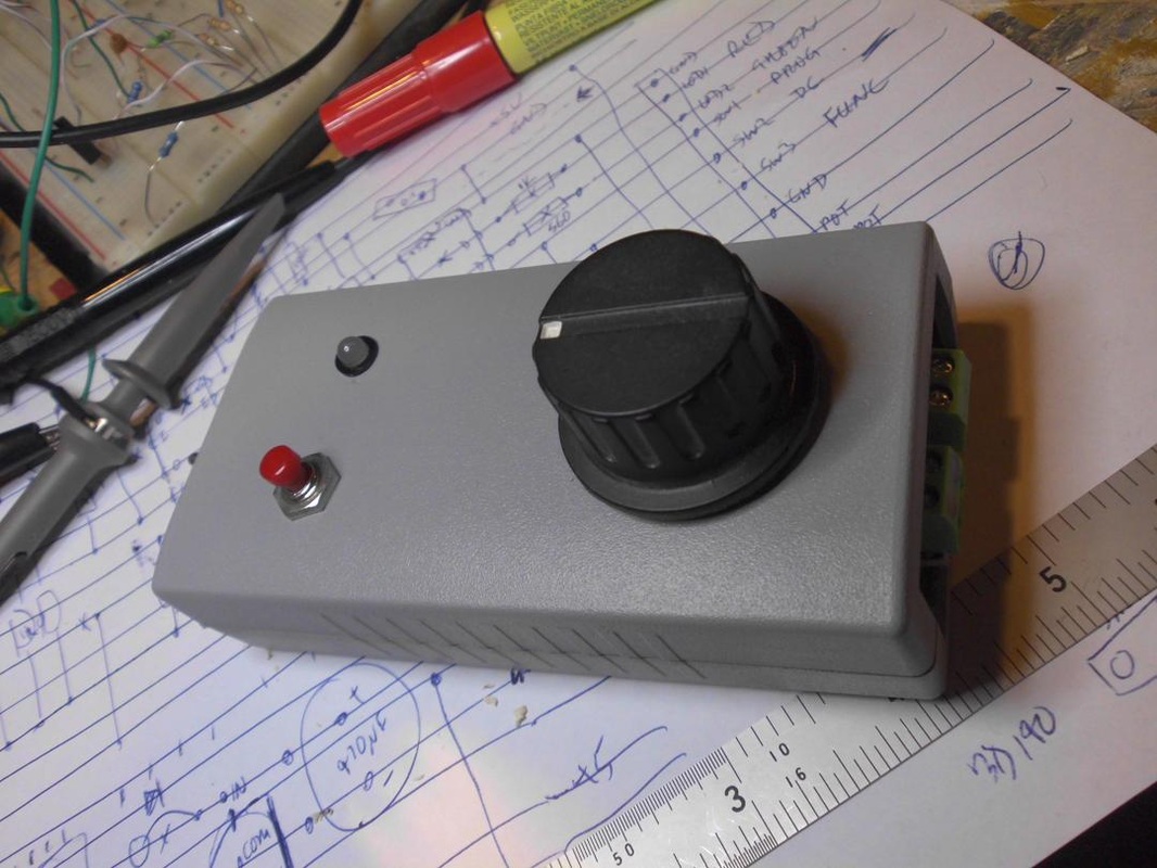
The controller is a hand-held unit with a centre-off speed knob (no reversing switch), a centre-off toggle switch to select the operating mode (DC, DCC or DCC-program), a push button used to program loco addresses and activate DCC functions, and a bi-colour red/green LED. The toggle switch is spring loaded in one direction (the program position), so you have to hold it here for at least one second to enter program mode.
This version is a minimal design - there is no LCD screen and only a single push button for controlling all DCC functions.
In either mode, the knob sets the train speed, optionally with inertia. There is a dead band in the centre that selects stop, right is forward, left is reverse. The LED shows yellow when stopped or green when the train should be moving. In flywheel-inertia mode, the train takes several seconds to accelerate or decelerate to or from full speed. In full-inertia mode, the knob acts as a throttle when on one side, selects coast when in the centre, braking when on the other side, and the knob must be returned to centre (brake release) before the train can be restarted.
If an overload occurs, the LED shows red and power is cut for about a tenth of a second. This test is repeated about 10 times a second until the fault is cleared.
In DC mode, push the function button 2, 3, or 4 times to set the inertia mode to off, flywheel or full. Pushing the button 8 times reverses the direction sense of the knob (e.g. so left is forward). These settings then also apply in DCC mode.
In DCC mode, the controller broadcasts the inertia-based speed and direction commands to all known loco addresses, so DCC locos should behave just like their DC cousins. If the DCC loco has its own inertia settings, the most extreme settings dominate (in practice, the loco settings). For an emergency stop, hold the function button down.
DCC functions can be toggled by pressing the function button one time more than the function number. To active F3, press the button 4 times. Change F0 by pressing the button once. A function can be pulsed rather than toggled by holding down the button on the last press - it stays active until released.
The controller broadcasts commands to as many as 33 different locos. It always broadcasts to address 3 (the default). All other loco addresses must be programmed into the handset. This only needs to be done once when a new loco is acquired - the list is stored in EEPROM for future use.
To add a loco address to the list, hold the spring-loaded mode switch in the program position until the LED starts flashing green. A new loco address can then be entered one digit at a time using the function button. For each digit, press the button that many times (10 for a zero), then pause - the LED will give a single red pulse to say that the digit has been accepted. Repeat for each additional digit. When done and ready to confirm the result, press and hold the program switch again until the LED pulses red. To cancel, just wait until the unit times out. A 2-digit loco address will normally be used for addresses up to 127, and 4-digit addresses for larger numbers. To force a 4-digit address, enter a leading zero.
To clear the loco list, enter program mode hold then hold the program switch over until the LED pulses red once, then do it a second time.
The Circuit
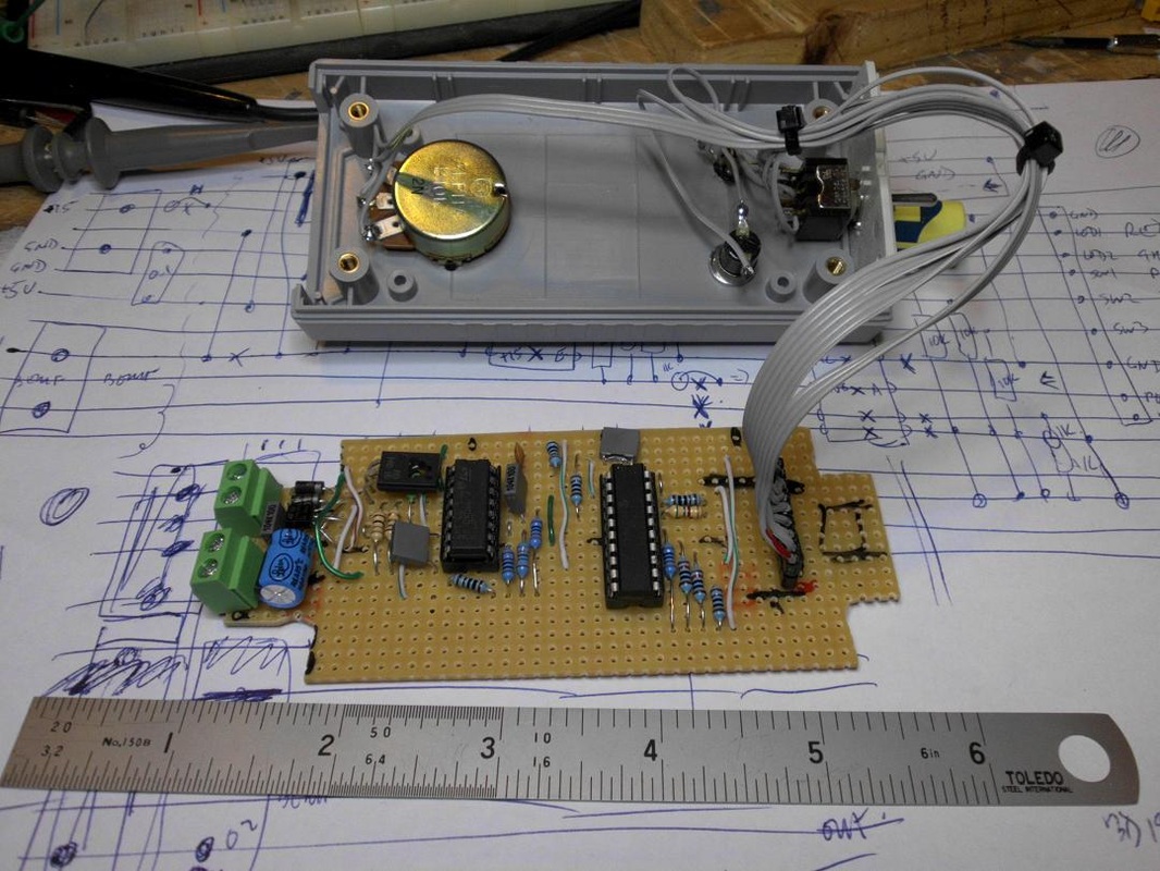
The circuit design is very conventional. A PIC16F690 drives a L293D driver chip. There is a potentiometer and a handful of switches and LEDs. There is a current sense circuit on the 15V input to the L293D to check for overloads. Because of processing speed limitations in DCC mode, I set this up as a digital input with a hard-wired current limit set to about 1A, rather than reading an analog input with a limit in software.
One subtle point is how the H bridge chip is driven. In DCC mode, the enable lines are set high and the drive inputs are PWMed. In DC mode, it is the other way round. This is necessary to get the correct AC waveform for DCC where the rails are pulsed between +- and -+, whereas a DC controller plays much better with others when pulsing between +- and off.
The PWM hardware in the PIC16F690 is pretty standard - most chips will provide the same basic features. However, if you use an Arduino I would not expect the software library to give you sufficiently fine control of the hardware - you will need to bypass the library and drive the PWM hardware directly. The pulse timing and interrupt handling are also quite critical, so I expect that these would also need to bypass the libraries.
Note: the circuit diagram should have a 10K pulldown resistor added on the H-bridge enable line.
DC PWM Timing
A basic DC square wave PWM is very easy to program, but the high-voltage square pulses can be quite harsh on small motors. They will certainly growl and sing loudly. This controller uses a much gentler and quieter trapezoidal pulse shape, ramping up to full voltage, staying there for a while, then ramping down again. In practice this is down by recursively PWMing each PWM pulse. The final pulse rate is approximately 124 Hz, or 8064 microseconds. Each pulse is broken up into 56 subpulses each of 144 microseconds (to correspond to the 28 DCC speed steps). Rather than just being set on or off, each of these subpulses is separately PWMed by the hardware, with the state of each subpulse set by a 144us timer interrupt routine. Each subpulse consists of three 48 microsecond timer periods PWMed at 0, 25%, 50%, 75% or 100%. This frequency is high enough that motors see the result as a changing voltage rather than a series of pulses. This is shown pictorially on the circuit diagram.
DCC PWM Timing
The NMRA DCC standard defines a one bit as 58us on followed by 58us off. A zero bit is at least 100us on followed by at least 100us off. I set the hardware timer to a period of 116us. A one bit is then one timer period PWMed at 50% duty cycle. A zero bit is two timer periods, 100% followed by 0%. The interrupt routine maintains byte value and bit count variables, and ensures that all bits of each byte are sent out in sequence. This typically takes 1-2 milliseconds, giving the higher-level code plenty of time to come up with the next byte. If not ready in time, the interrupt routine sends out all-ones interpacket bytes. The bytes area ctually 9 bits long, with 8 data bits and 1 verification bit.
DCC / DC PWM Source code in C
I have provided the source code for anyone interested. Free for non-commercial use. No warranty!
I have provided the source code for anyone interested. Free for non-commercial use. No warranty!
| ndcc0.c |
Circuit Diagram

Hybrid DCC / DC PWM Controller
Note: the circuit diagram should have a 10K pulldown resistor between RC3 and ground.
