Electronics - Dapol Semaphore Signals
The new Dapol N gauge semaphore signals are very nice, but their control mechanism seems a little awkward to me. Each signal has four wires: 2 for a constant 16V AC supply, and 2 that are intended to go to a push button that activates the signal. This should be pushed for no longer than 1 second at a time. Each push tells the signal to change its state: from danger to clear or from clear to danger. There is no way to set the signal to a defined state (i.e. danger).
I am currently installing 6 of these on the new layout. If they continue to work reliably, I'll increase that to 12 in the near future.
UPDATE: I tried 5 of these on my automatic main line, but was unhappy with the result and will end up using 4-aspect colour lights instead. The signals did work OK (although I managed to destroy one), but they didn't quite look right. The arms tended to move down to 60-70 degrees from vertical (prototype standards say 45 +/- 10 degrees or else the signal is considered defective). This is clearly a design decision on Dapol's part, not a random fault, since the green spectacle is oversized to work properly in this position. Also, the bright white LED was overpowering, even when run at reduced voltage (12V AC). An over-large gap between the lamp and the signal arm means that the lamp tended to illuminate everything nearby with a vertical band of bright blue-white light, and the glare when viewed from an angle made it hard to tell what state the signal was in. Also, the base plate is enormous for N (larger than a 10' wagon), and would have to be cut down for installation in tight locations .
Overall, they are not a bad model but the shortcomings added up to too much for me. I suspect that the OO versions would be better: the mechanism and base plate are identical, so the signal's larger size would likely reduce the 60-70 degree and side light issues. It almost looks like it was originally a OO design that was adapted for N.
I ended up using the colour light kits from CR Signals (see Plymouth Citadel Signals).
-----------
The following circuit allows a toggle switch to be used to control the signal. This switch could be in a simulated lever frame or on a conventional panel. Each time the switch is moved (either on or off) , it turns on a 12V relay for about half a second, which simulates the push button activation the signal requires.
Toggle Switch Control Circuit
The circuit works by using the relay as a resistor to charge a capacitor. When you turn the switch to the on position (up on the diagram), there is 12V on one side of the relay and 0V in the capacitor on the other side, so there is 12V across the relay, which then turns on. The voltage on the capacitor slowly rises as it charges through the relay. When the capacitor reaches about 8 volts (2/3rds charge), there will only be 4 volts left across the relay which will then turn off. This happens after about half a second. The capacitor will continue to charge to the full 12V for the next second or so. After this, everything is static: the whole circuit is at 12V, so no current flows and everything can stay this way indefinitely.
When the switch is turned off again, the capacitor starts to discharge through the relay and the same thing happens in reverse. The relay has 12V across it, so turns on. After half a second or so, the voltage drops to 4V and the relay turns off. The capacitor continues to discharge until everything is back to 0V.
A double pole switch is used since most small relays have a polarized coil with plus and minus pins. This circuit will work for non-polarized relays too.
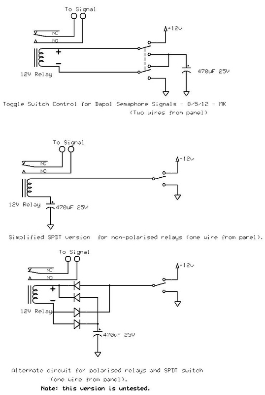
Wiring diagram for Dapol signal control. The upper diagram will work with any type of relay. The middle version will work with non-polarised relays, and only requires one wire from the panel switch. The lower version of the circuit allows one-wire control with a polarised relay at the cost of a few diodes. Note that this third circuit has not been tested.
Caveats
The capacitor value is given as 470uF. This should work for most 12V relays. The goal is to keep the relay on for half a second, but anything from 0.25 to 1 second seems OK. If it stays on too long, use a 220uF or 330uF capacitor instead. If not long enough, try 680uF or even 1000uF. Regardless of its value, the capacitor should have a voltage rating of 25V or more.
There is no way of knowing what state the signal is really in, even if the toggle switch is set up as red/green or danger/clear. You will find that the switch and signal get out of sync with each other. This can happen if the switch is moved when the layout power is off. Another example is if the switch is already on when the layout power is turned on, the relay will trigger and the signal will make a spurious movement. In either case, the signal can be resynchronized by simply moving the switch, letting the signal start to move, then quickly putting the switch back to its previous position. The signal will not see the second event.
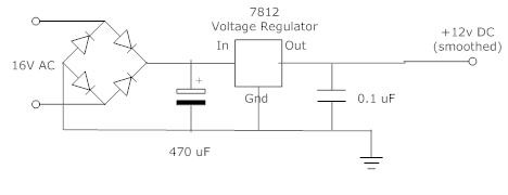
The circuit requires smoothed or regulated DC, not the usual railway modeller's full-wave DC from a transformer and rectifier. You can find a circuit for a fully regulated 12V supply in the data section of most electronics store catalogs, but I have included one below just in case. One such power supply can handle any number of signals.
The capacitor value is given as 470uF. This should work for most 12V relays. The goal is to keep the relay on for half a second, but anything from 0.25 to 1 second seems OK. If it stays on too long, use a 220uF or 330uF capacitor instead. If not long enough, try 680uF or even 1000uF. Regardless of its value, the capacitor should have a voltage rating of 25V or more.
There is no way of knowing what state the signal is really in, even if the toggle switch is set up as red/green or danger/clear. You will find that the switch and signal get out of sync with each other. This can happen if the switch is moved when the layout power is off. Another example is if the switch is already on when the layout power is turned on, the relay will trigger and the signal will make a spurious movement. In either case, the signal can be resynchronized by simply moving the switch, letting the signal start to move, then quickly putting the switch back to its previous position. The signal will not see the second event.
The circuit requires smoothed or regulated DC, not the usual railway modeller's full-wave DC from a transformer and rectifier. You can find a circuit for a fully regulated 12V supply in the data section of most electronics store catalogs, but I have included one below just in case. One such power supply can handle any number of signals.