Electronics - Synchronized Fast Clocks
If you want to operate a layout to a timetable, you really need a fast clock to compensate for the short distances and keep the operators busy. Fast clocks typically run at speeds of x4 or x6. A medium or large layout really needs multiple clocks so that all operators can see one, all of which need to be synchronised with one another. I have seen people using computers with multiple monitors, hand-built LED digital clocks and real historic railway clocks for this purpose, but all of these are hard to come by or require a great deal of work.
My solution is to modify standard the cheap analog electric clocks that you can buy in your local department store, anything from small alarm clocks to replica station clocks, and build a simple circuit to drive one or more of these clocks in a synchronised fashion. The clocks don't even have to be identical, though they do have to have similar mechanisms. There are sites on the web that sell kits for doing this, but these tend to be high-end solutions, will generally cost you $100 or more, and still require you to do most of the work yourself. My circuit is about as simple as you can get for this application - basically just a standard NE555 timer plus one capacitor per clock.
Caveats
- The circuit is designed for analog clocks powered by a 1.5V battery that advance the second hand in jumps, once per second, with the traditional tick-tock sound
- I have tried it on two different manufacturer's mechanisms, and it should work fine with any similar type. Obviously, I cannot be sure of this.
- The circuit should work as is with up to five clocks, and has been installed and used successfully with four. If more are required, then a transistor driver stage would need to be added between the 555 output pin and the clocks.
- I have tested speeds of up to x10, which is the limit that the circuit can handle.
Clock Theory
There are two basic kinds of battery-operated analog clock mechanism that I know of, both using a small stepper motor. One type pulses the motor once per second, so the second hand moves in 1-second jerks and the clock makes the traditional and distinctive tick-tock sound. The other pulses the motor more rapidly (16 times a second in the one I looked at), effectively working like a normal motor, and gives a smooth silent motion. The circuit described here only works with the 1-second tick-tock type of mechanism.
The original circuit in each clock generates one pulse per second to drive the stepper motor. Each pulse is about 30 milliseconds long, is about 1.5V (the battery voltage), and the pulses are alternately positive and negative. This is where the tick-tock sound comes from. The mechanism starts and stops moving on every pulse, so the clock can be accelerated by simply increasing the pulse rate. Eventually the pulses get so close together that the mechanism doesn't get a chance to stop before the next pulse - this is where the x10 maximum speed limit arises.
The smooth silent type of drive cannot be accelerated significantly this way since the drive pulses are already so close together that the mechanism just keeps moving continuously. The test clock of this type pulsed at 16 times per second. It would probably be possible to increase this by 50% or so, but I feel this would be too small an increase to be worth bothering with (or a more sophisticated circuit would be needed).
Modifying the Clock
Each clock needs to be modified slightly - you need to connect two wires to the stepper motor coil to allow it to be connected to the control circuit. This will not affect the operation of the clock - if you reinstall the battery, the clock will still work in normal x1 time.
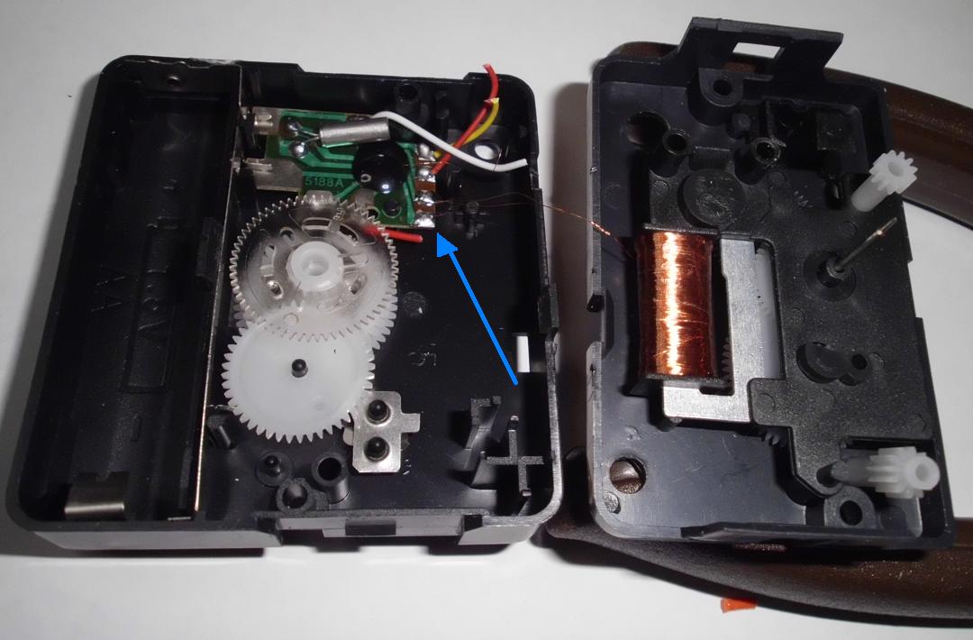
You will have to completely disassemble the clock mechanism and put it back together again. I found that this was as bad as disassembling a model loco - with even more loose gears! Some mechanisms are much worse than others. By far the easiest was the replacement mechanism I got from Jaycar Electronics (cat no. XC0100). Keep a 1.5V battery handy, and test the clock before and after working on it. I recommend doing a full disassemble-reassemble-test cycle before trying to solder the wires.
While you have the unit disassembled, it is a good idea (although not essential) to check the resistance of the stepper coil with a multimeter. Both of my units were about 220 ohms, and anything between 150 and 300 ohms should be OK and not require any circuit tweaks.
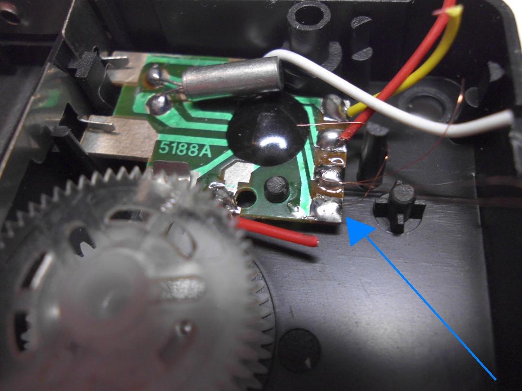
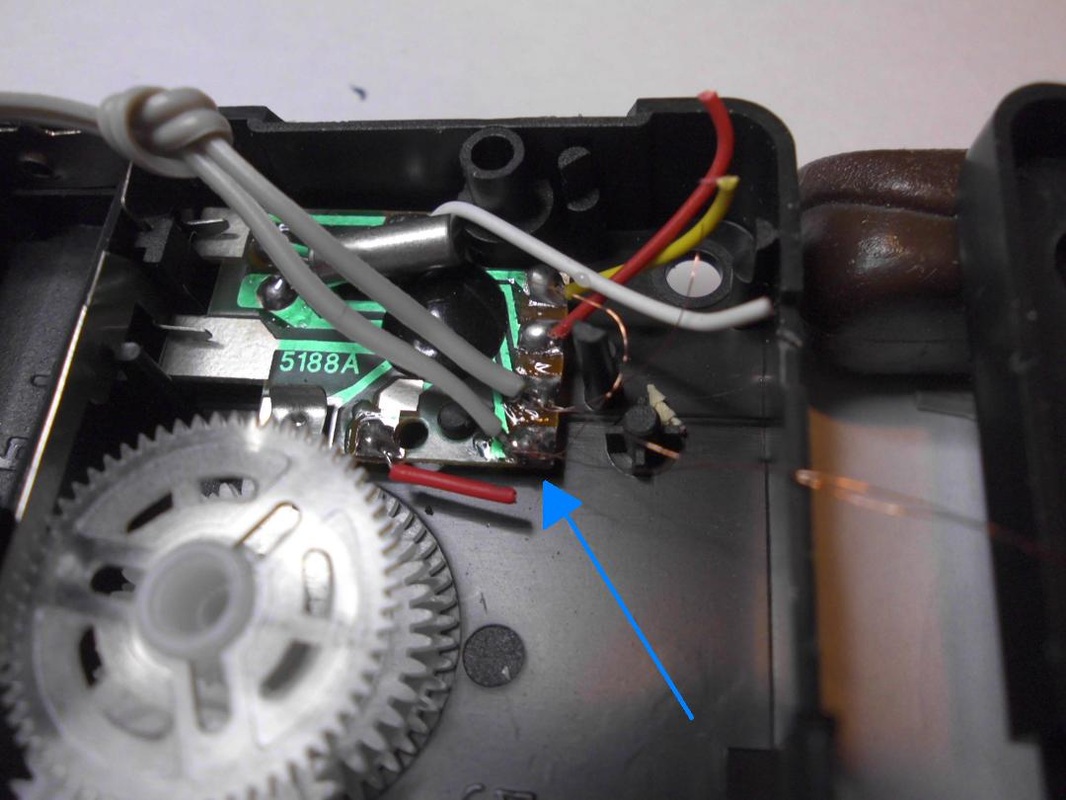
When you remove the stepper motor coil, you will find that two very thin copper wires go to a pair of solder connections on a circuit board. You will need to solder a wire to each of these two connection points. Use the thinnest multi-strand wire you have (I used two wires from a length of grey IDC ribbon cable), and make sure that the copper wires to the coil don't come unsoldered (yes, it happened to me). Pre-tin the ends of the wires before soldering them. You will need to make some provision for leading the wires out of the clock, probably by cutting a slot in the case. Strain relief is also recommended - tie a knot in the cable just inside the case so that nothing breaks if you pull on the wire. I suggest terminating the wires in a small plug (I used IC socket strip - see the page on Connectors for an example).
After reassembling the unit, check for correct normal operation with a battery. Then remove the battery, and check the resistance across the two new wires - it should be the same as you measured earlier.
After everything is working, you may want to remove the second hand - it is useful during testing but watching it race and bounce around at high speed can be distracting.
There are two basic kinds of battery-operated analog clock mechanism that I know of, both using a small stepper motor. One type pulses the motor once per second, so the second hand moves in 1-second jerks and the clock makes the traditional and distinctive tick-tock sound. The other pulses the motor more rapidly (16 times a second in the one I looked at), effectively working like a normal motor, and gives a smooth silent motion. The circuit described here only works with the 1-second tick-tock type of mechanism.
The original circuit in each clock generates one pulse per second to drive the stepper motor. Each pulse is about 30 milliseconds long, is about 1.5V (the battery voltage), and the pulses are alternately positive and negative. This is where the tick-tock sound comes from. The mechanism starts and stops moving on every pulse, so the clock can be accelerated by simply increasing the pulse rate. Eventually the pulses get so close together that the mechanism doesn't get a chance to stop before the next pulse - this is where the x10 maximum speed limit arises.
The smooth silent type of drive cannot be accelerated significantly this way since the drive pulses are already so close together that the mechanism just keeps moving continuously. The test clock of this type pulsed at 16 times per second. It would probably be possible to increase this by 50% or so, but I feel this would be too small an increase to be worth bothering with (or a more sophisticated circuit would be needed).
Modifying the Clock
Each clock needs to be modified slightly - you need to connect two wires to the stepper motor coil to allow it to be connected to the control circuit. This will not affect the operation of the clock - if you reinstall the battery, the clock will still work in normal x1 time.
You will have to completely disassemble the clock mechanism and put it back together again. I found that this was as bad as disassembling a model loco - with even more loose gears! Some mechanisms are much worse than others. By far the easiest was the replacement mechanism I got from Jaycar Electronics (cat no. XC0100). Keep a 1.5V battery handy, and test the clock before and after working on it. I recommend doing a full disassemble-reassemble-test cycle before trying to solder the wires.
While you have the unit disassembled, it is a good idea (although not essential) to check the resistance of the stepper coil with a multimeter. Both of my units were about 220 ohms, and anything between 150 and 300 ohms should be OK and not require any circuit tweaks.
When you remove the stepper motor coil, you will find that two very thin copper wires go to a pair of solder connections on a circuit board. You will need to solder a wire to each of these two connection points. Use the thinnest multi-strand wire you have (I used two wires from a length of grey IDC ribbon cable), and make sure that the copper wires to the coil don't come unsoldered (yes, it happened to me). Pre-tin the ends of the wires before soldering them. You will need to make some provision for leading the wires out of the clock, probably by cutting a slot in the case. Strain relief is also recommended - tie a knot in the cable just inside the case so that nothing breaks if you pull on the wire. I suggest terminating the wires in a small plug (I used IC socket strip - see the page on Connectors for an example).
After reassembling the unit, check for correct normal operation with a battery. Then remove the battery, and check the resistance across the two new wires - it should be the same as you measured earlier.
After everything is working, you may want to remove the second hand - it is useful during testing but watching it race and bounce around at high speed can be distracting.


The Circuit
The circuit is basically just a standard NE555 timer set up to generate a repetitive pulse train. This gives one pulse every two (scale) seconds. The start of the pulse is the tick, and the end of the pulse is the tock. It is easy to set up the 555 timer to vary the length of either the tick or the tock, but not both, so the length of the tick is variable but the tock is fixed at a value suitable for the maximum speed of x10. At low speeds, the clock will sound like "tock-tick-pause, ..." instead of a more normal even beat.
The trick to this design is how this single square-wave pulse from the NE555 gets converted into the two stepper pulses, positive followed by negative. Each clock mechanism requires a 68uF capacitor (or a 47 and 22 paired, since 68uF caps are hard to come by) between it and ground. When the NE555 output goes high and the pulse starts, current flows through the stepper coil and begins to charge the capacitor. As the capacitor fills up, the voltage across the coil is reduced, and dies away to near zero after 100 milliseconds or so when the capacitor is fully charged. When the pulse ends and the timer output goes low, the same thing happens in reverse - the capacitor discharges through the stepper coil generating an equivalent but inverted pulse. The pulse shapes seen by the stepper motor are very different to the normal clock circuit, with a higher start voltage followed by a gradual reduction, but the net effect and total energy is about the same. This is similar to what happens when using a CDU to drive a point motor. I use much the same double-action trick when driving Dapol semaphore signals and my Peco point motors.
Each clock needs its own capacitor and a voltage-limiting resistor. The clock mechanism was designed to run off a single 1.5V battery and receive 1.5V pulses. The resistor is chosen to give an initial peak voltage of about 2.5-3.0V which then rapidly falls and averages out to the same 1.5V over the full length of the pulse. The component values of 220 ohms and 68 uF worked well in testing, but you may need to alter them for specific mechanisms, especially if the coil resistance is outside the range 150-300 ohms. Try to make the resistor value roughly the same as the stepper coil resistance, and adjust the capacitor value to compensate and keep the pulse duration the same (C = 15000 / R, e.g. 68uF = 15000 / 220 ). If necessary you can have different values for each individual clock.
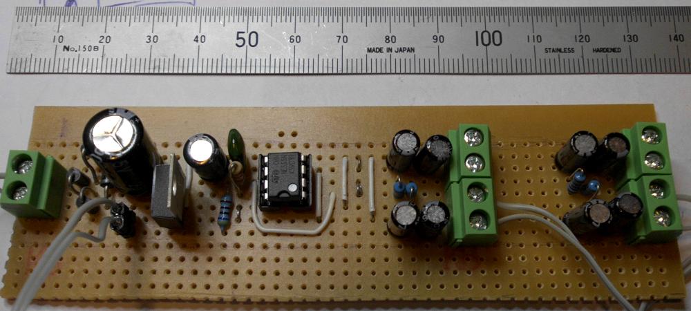
The NE555 timer chip must by the bipolar version with the NE prefix, not the CMOS type, since this type is designed to directly power relay-type loads with up to 100mA. Each clock's drive pulse peaks at about 20mA, so the circuit can handle four clocks, possibly five. Additional clocks could be handled by adding a transistor output stage.
A 9V regulated power supply is used, since this can be reliably derived from the usual railway 12V DC or 16V AC.
There are two ways to select the speed: using a potentiometer to give any arbitrary speed in the range x1 to x10, or a rotary switch selecting different resistors to give one of a few fixed selected values. If you use the pot, you will have to calibrate it and mark appropriate settings on the panel. You will also need a separate on/off switch to turn off power to the circuit (or activate the reset pin on the 555). If you use a two-pole rotary switch, you can have an OFF position on the second pole do the same thing.
If you use a rotary switch, the following resistor values should be used to get the correct speeds:
x2 - 12K
x3 - 6K8
x4 - 4K7
x5 - 3K3
x6 - 2K2 (we actually want 2K4, so if fussy then use a pair in series: 2K2 + 220)
x8 - 1K2
x10 - 470
The circuit is basically just a standard NE555 timer set up to generate a repetitive pulse train. This gives one pulse every two (scale) seconds. The start of the pulse is the tick, and the end of the pulse is the tock. It is easy to set up the 555 timer to vary the length of either the tick or the tock, but not both, so the length of the tick is variable but the tock is fixed at a value suitable for the maximum speed of x10. At low speeds, the clock will sound like "tock-tick-pause, ..." instead of a more normal even beat.
The trick to this design is how this single square-wave pulse from the NE555 gets converted into the two stepper pulses, positive followed by negative. Each clock mechanism requires a 68uF capacitor (or a 47 and 22 paired, since 68uF caps are hard to come by) between it and ground. When the NE555 output goes high and the pulse starts, current flows through the stepper coil and begins to charge the capacitor. As the capacitor fills up, the voltage across the coil is reduced, and dies away to near zero after 100 milliseconds or so when the capacitor is fully charged. When the pulse ends and the timer output goes low, the same thing happens in reverse - the capacitor discharges through the stepper coil generating an equivalent but inverted pulse. The pulse shapes seen by the stepper motor are very different to the normal clock circuit, with a higher start voltage followed by a gradual reduction, but the net effect and total energy is about the same. This is similar to what happens when using a CDU to drive a point motor. I use much the same double-action trick when driving Dapol semaphore signals and my Peco point motors.
Each clock needs its own capacitor and a voltage-limiting resistor. The clock mechanism was designed to run off a single 1.5V battery and receive 1.5V pulses. The resistor is chosen to give an initial peak voltage of about 2.5-3.0V which then rapidly falls and averages out to the same 1.5V over the full length of the pulse. The component values of 220 ohms and 68 uF worked well in testing, but you may need to alter them for specific mechanisms, especially if the coil resistance is outside the range 150-300 ohms. Try to make the resistor value roughly the same as the stepper coil resistance, and adjust the capacitor value to compensate and keep the pulse duration the same (C = 15000 / R, e.g. 68uF = 15000 / 220 ). If necessary you can have different values for each individual clock.
The NE555 timer chip must by the bipolar version with the NE prefix, not the CMOS type, since this type is designed to directly power relay-type loads with up to 100mA. Each clock's drive pulse peaks at about 20mA, so the circuit can handle four clocks, possibly five. Additional clocks could be handled by adding a transistor output stage.
A 9V regulated power supply is used, since this can be reliably derived from the usual railway 12V DC or 16V AC.
There are two ways to select the speed: using a potentiometer to give any arbitrary speed in the range x1 to x10, or a rotary switch selecting different resistors to give one of a few fixed selected values. If you use the pot, you will have to calibrate it and mark appropriate settings on the panel. You will also need a separate on/off switch to turn off power to the circuit (or activate the reset pin on the 555). If you use a two-pole rotary switch, you can have an OFF position on the second pole do the same thing.
If you use a rotary switch, the following resistor values should be used to get the correct speeds:
x2 - 12K
x3 - 6K8
x4 - 4K7
x5 - 3K3
x6 - 2K2 (we actually want 2K4, so if fussy then use a pair in series: 2K2 + 220)
x8 - 1K2
x10 - 470
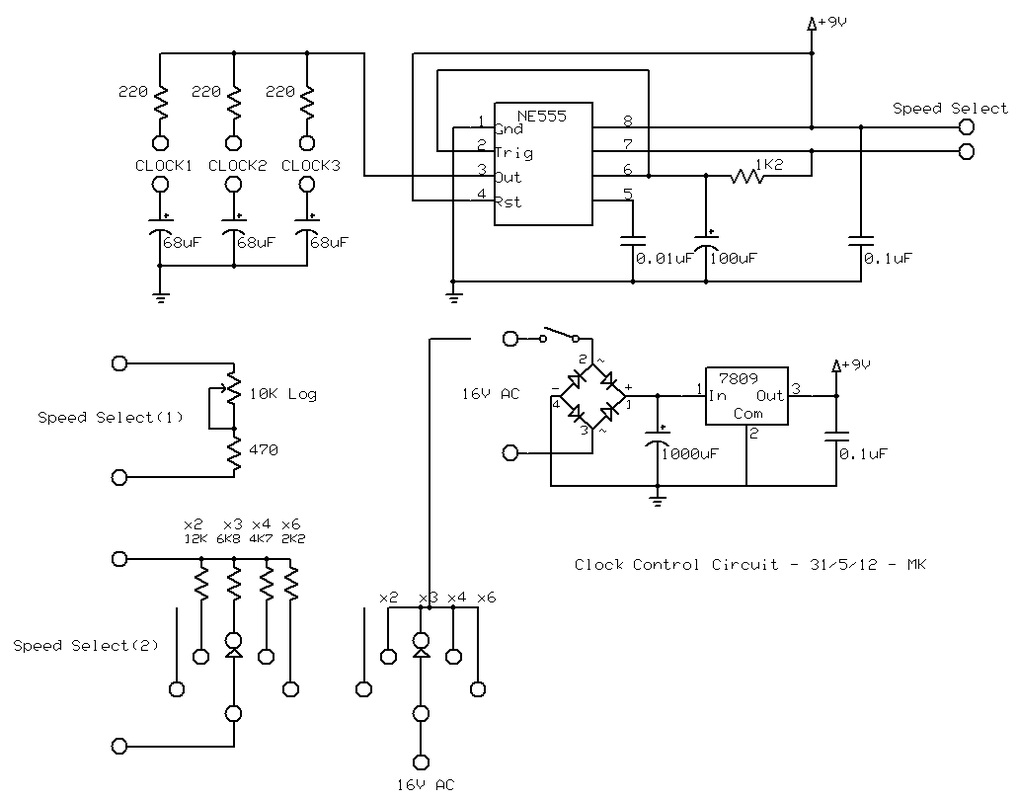
Circuit diagram for synchronised clock controller. Two alternative speed selection options and on/off options are shown.
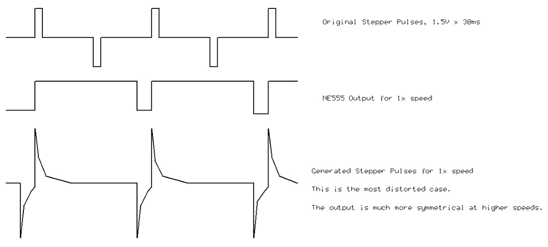
Stepper motor drive waveforms.
