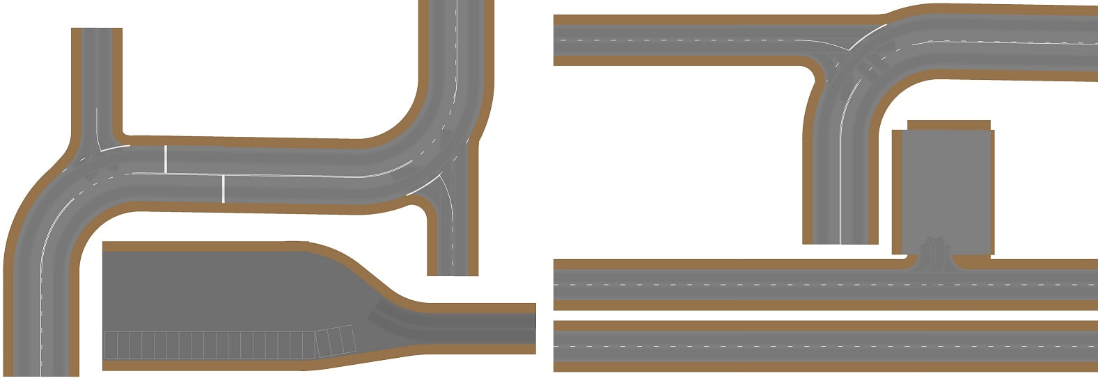
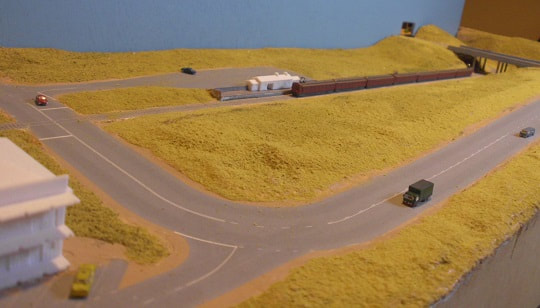
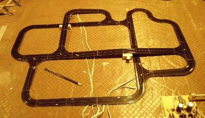
Getting the roads working is one thing. Getting decent-looking road markings is something else entirely, especially when they need to line up with the underlying linear motor track.
I ended up defining a small computer language to describe the roads, then writing a small Windows program to read this and generate the graphics. These were then printed with an inkjet onto self-adhesive label paper, sprayed with a couple of coats of matte acrylic, cut out and stuck to the track or cardboard foundation, then sprayed with more matte acrylic.
I ended up defining a small computer language to describe the roads, then writing a small Windows program to read this and generate the graphics. These were then printed with an inkjet onto self-adhesive label paper, sprayed with a couple of coats of matte acrylic, cut out and stuck to the track or cardboard foundation, then sprayed with more matte acrylic.
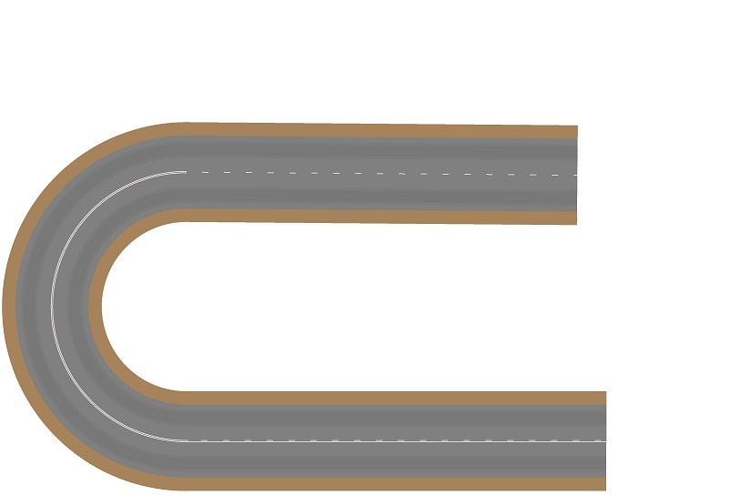
Here is the script used to generate this length of roadway:
// set DPI for decent resolution
dpi 300
// brown verge at edge of road - 5mm wide, RGB colour=0xa68e5b (pale brown)
margin 5.0 5b83a6
// Page 1
// start new page, with size in mm, sized for A4 minus default margins in Paint
boundary 271.0 184.0
// set drawing step size to 0.5mm, and line marking RGB colour=0xf3ece8 (off-white)
line 0.5 e8ecf3
// set road width to 27mm and base RGB colour=0x808080 (medium grey)
road 27.0 808080
// define dirty/worn traffic lanes to be 4.0mm wide, offset 8.5mm from road centre
lane 8.5 4.0
// Curve at LH end
// Set start position= bottom right, direction=180 degrees (facing left)
start 225 20 180
// draw 155mm of straight road, markings=0 3 0 (no edges, solid+broken), dirty lanes
draw 155.0 0.0 0 3 0 1
// draw 157+mm of curve, right 50mm radius, markings=double white, dirty lanes
// (funny length works out to 180 degrees)
draw 157.0796 -50.0 0 5 0 1
// draw 145mm of straight road, markings=broken, dirty lanes
draw 145.0 0.0 0 1 0 1
// write this to a file, ready to be loaded into Microsoft Paint.
write test.bmp
 RSS Feed
