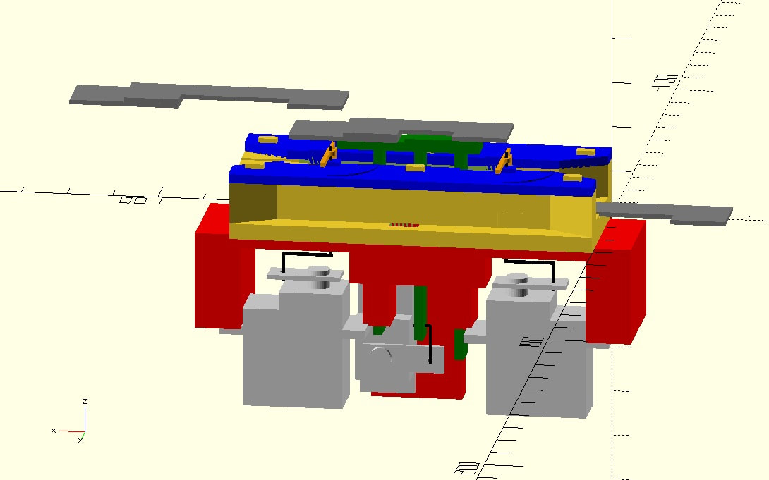
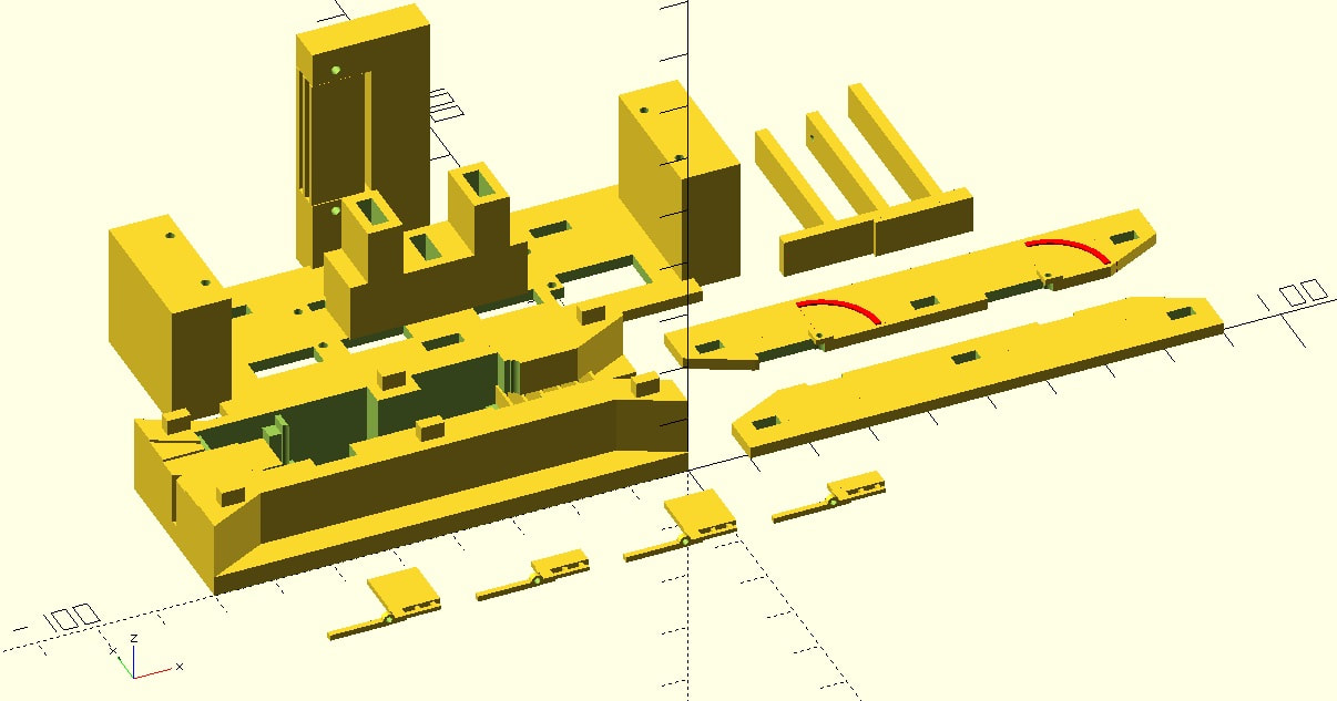
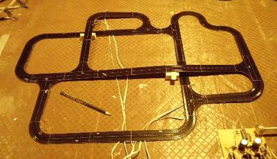
Here are some CAD drawings of the lock mechanism. All the parts are 3D printed, designed around three small servos and the requirements of the linear motor track. The elevator legs have been stretched in this image, since the elevator and track should obviously be hidden within the lock chamber. The picture below the fold shows the actual parts as built. Comments are closed.
|
Overview
British and Australian model railway layouts in T, N and OO. My Layouts
Friends' Layouts
Main Articles
Categories
All
Archives
April 2024
AuthorMartin Kaselis |
- Home
- My Linear Motor Layouts
- My Conventional Layouts
- Other Layouts
- T Gauge
-
Electronic Tips
- Blue Pill - Bare Metal C Programming
- Working Roads
- Hybrid DC - DCC Controller
- Using LEDs
- Connectors
- Controlling the Fleischmann Turntable
- Constant Brightness Tail Lamps (OO scale)
- Point Motors and Relays
- Point Motors and Toggle Switches
- Dapol Signals
- Colour Light Signals and Automation
- Synchronized Fast Clocks
- Wire Sizes and Voltage Drop
- DC Controllers
- Controller Types
- Feedback Controllers
- Working Level Crossing
- General Tips
- 3D Printing
- Contact
- Links