Plymouth Citadel - Trackwork (and some Electrics)
The layout uses mostly Peco code 55 track. The track at the station/lower-level board join uses two Peco Settrack curves as joiner pieces (3rd and 4th radius work out perfectly for the 12 and13 inch curves here). The turntable is a Fleischmann electric unit (model 9152). The Fleischmann track is just about impossible to join to Peco code 55, but links up well enough with Peco code 80 using Fleischmann fishplates, so code 80 is used for the turntable storage roads and the end section of the two turntable access roads, which then join to code 55.
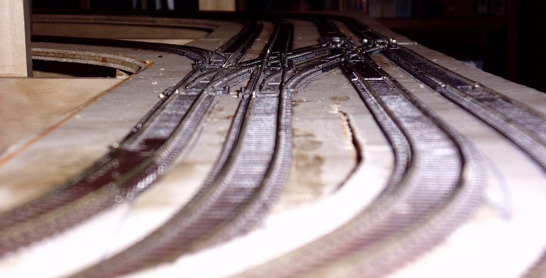
The track plan uses a total of 28 pieces of code 55 pointwork, including two diamond crossing, two slips and three of the new three-way points (good timing on my part). A total of 43 yards (I think) of flex track were used. The full length of the out-and-back run is 2 scale miles.
I prefer the code 55 track to the older code 80 partly because of the appearance and range of pointwork, but I also find it easier to lay the flexi track. When you bend it, it tends to stay in the desired shape instead of acting like a spring. Only one side of the code 55 flex has cutouts under the sleepers, so the track bends better one way than the other.

Wiring the track
I currently subscribe to the "solder a wire to every piece of rail" philosophy when laying track. On previous layouts, I used a slightly weaker form: every second piece of rail as long as there were metal rail joiners at both ends. I solder to the underside of the track before placing it: cut away the plastic base between two sleepers (or widen an existing gap), apply a small blob of solder, then solder on a piece of tinned wire. I use light multistrand wire, generally either light hookup wire or wire extracted from a length of rainbow cable. If a solder tail is formed, file it down flat with the sleeper base. When ready to lay the track, drill two holes in the track bed and feed the wires through.
During track laying, I just let a forest of wires accumulate and dangle. When I start the wiring, I fit tag boards at suitable places under the board and then route and cable the wires to the appropriate tags. I generally use a standard 4 feet length of wire when laying track: this is long enough to reach a long way on an N gauge layout, and avoids having to splice a wire that ends up just a little too short. It does result in a fair bit of wasted wire when I get around to trimming to length.
I solder three wires to the underside of every point: one to each stock rail and one to the frog. It is the same technique as for flex track, but you have to be a little more careful, especially when selecting which sleeper section to use: stay well clear of the plastic check rails.
Point Motors
I have chosen to use the (relatively) new Peco low-power point motors on this layout.
On previous layouts, I used the Seep motors with the built-in switch for the frogs, but I found them awkward to work with. The Seep switch appears to have been designed for OO or N code 80 points. The blades of the code 55 points do not move as far, so the switch just barely moves far enough to work. This requires very fiddly, careful alignment when mounting the motor. Worse, the sliding washer on the switch seems to be able to drift a little with time, so I have found that a year or so later some of the switches have stopped working. In addition, the Seep motors require of lot of current to throw, needing heavy wiring, powerful CDUs and transformers, and making life difficult for me when trying to control them using electronics. I generally end up running them on 30V instead of the usual 20V.
I initially avoided the older Peco motors due to the difficulty in fitting the accessory switch, and the extra mechanical load it imposed on the motor. I now use separate relays for frog switching (and all sorts of other things), so that is not an issue. The new low-power motors only need half the power of the old Peco motors (and a quarter of that needed by the Seep motors), which simplifies many things. I can use normal light wire, 1A diodes instead of 3A, and a less powerful power supply that is also available for other tasks.
I make a small control board for each point motor with its own mini CDU and two latching relays. This lets me control the points using standard toggle switches from a simulated lever frame or diagrammatic panel instead of using push buttons, and provides 4 poles worth of switch contacts for routing frogs, section feeds, uncouplers, and other stuff through the pointwork. In Australia, many modellers use old telephone exchange relays as point motors. These control boards effectively convert Peco motors into such a relay.
Common Return
I use common return wiring, although in a fairly limited way. I rely very heavily on switching power through the pointwork, so in most of the station what should be the common rail is in fact connected to the frog of some set of points.
Fleischmann Turntable
The MPD has a Fleischmann turntable, configured with 12 roads. I do not particularly like the control system provided by Fleischmann - having to move the switch to specify which end of the table to power seems clumsy. After a good deal of thought and experimentation, I discovered how to drive the turntable directly from a rotary switch: when you move the switch to position 5, the turntable turns to road 5.
The turntable was modified to look more like a Great Western design by removing the cabin, handrails and steps (easy since they are all just press-fit), then adding two GWR-style over-girders made from a cannibalised Kato girder bridge. I looked at various ways to conceal the overly-deep turntable pit, but in the end just painted the original sides a dark murky grey.
